Contents
Introduction
In order to communicate, computers need to be connected using a network, and they need to speak the same language, which we refer to as a protocol. Computers began to be networked together in the middle of the 20th century, and it took less than 30 years to create the global ubiquitous network we know as the internet.
The language that every computer speaks, when it’s connected to the internet, is called TCP/IP. This protocol exists as a stack, consisting of four layers, each of which performs one specific function in the communication, and is abstracted entirely from the other layers. This allows communications protocols to be updated in one discrete section without having an effect on the rest of the stack.
Multiple Layer Model
When we talk about something occurring at one specific layer, references are generally made to the Open Systems Interconnection (OSI) 7 Layer model. The four layers of the TCP/IP stack map against the OSI layer model approximately according to Figure 0.1.
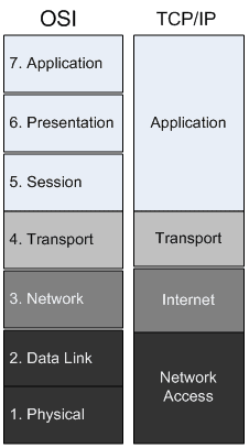
Figure 0.1 – OSI and TCP/IP layer mapping
One benefit of this layering is encapsulation. Rather than have each network-aware computer program manually create every bit of information that is transmitted over the network, layering allows every piece of the stack to concentrate on its own task, and rely on the abstraction of the next step by passing data down to the layer below it.
For instance, when communicating with a web site, the web browser doesn’t actually talk to the network card. It sends the data to the operating system, and the operating system talks to the network card, and the network card actually puts the bits on the network cable. At each step, encapsulation is added to the data by the next layer, so that when the information is on the network, it can be easily delivered, parsed, and displayed in our web browser.
The easiest way to visualize this is by using nested envelopes. If you send a letter to your friend, you will mail it in an envelope. If you include instructions for your friend to forward it to someone else, your friend might encapsulate your letter, along with its envelope, in a bigger envelope. The second friend might receive instructions to forward that package as well. Each time the message is forwarded, it receives a new envelope. When the recipient receives the package, they examine each envelope from the outside in. This is what happens when the remote machine receives your web request. They must unwrap from the outside in to get to the data, as well.
The first, or physical, layer is concerned with the networking medium or devices. Broken or unplugged network cables, wireless interference, and unpowered network equipment are all considered layer one problems.
Layer one presents itself as bits of electricity, or physical connectivity. There is no specific addressing; there are only signals that indicate on and off. Hubs and repeaters are considered layer one devices, because they don’t examine any network traffic, they merely replicate the bits that they receive.
Layer two, the data link layer, relies on the physical layer, and allows communication between devices. One device identifies itself and others using Media Access Control (MAC) addresses. Every network card is assigned a 6 byte address that is typically expressed as 6 pairs of hexadecimal digits, separated by a colon or dash. An example may look like this:
A1:B2:C3:D4:E5:F6
The first three bytes, in this case A1B2C3, distinguish the manufacturer of the network card, and the last three bytes, D4E5F6, are an identifier specific to this network card, which nearly guarantees that the MAC address in its entirety is unique.
Switches and bridges operate at layer two. Switches accept traffic in one port, examine the destination MAC address, and then forward the frame to the next appropriate port. Layer 2 devices maintain a table, in their memory, of MAC addresses that they’ve seen, mapped to the port that the device was seen on. If the switch receives a frame destined for an MAC address that it hasn’t seen, it forwards that packet to all ports, except the one it received it on.
Layer three, the network layer, is otherwise known as the IP portion of TCP/IP, and is currently undergoing a transition. The version discussed in this book, for the most part, will be IPv4, where IP addresses consist of 32 bits, allowing around 2 billion usable addresses. These addresses are almost all assigned to organizations, and the stock of addresses is nearing depletion. To mitigate this, IPv6 is being deployed. IPv6 uses 128 bits in its address, and it is believed that this will remedy the issue for the foreseeable future.
Routers operate at layer three and these devices segment networks into subnets. Devices on different subnets need a router to communicate. These routers are multiport devices that maintain route tables, enabling them to make decisions on where is best to forward traffic, based on the destination IP address.
Layer four, the Transport layer, dictates communication settings, such as error control and segmentation. The TCP of TCP/IP is a layer four protocol and specifies a “reliable” connection, meaning packets must be numbered, and any that are lost in transit will be resent. TCP is connection-oriented and requires a three-way handshake to begin communication, and another specific exchange to tear down connections.
UDP, another common protocol, is “unreliable”, meaning packets won’t be retransmitted, and it is also connectionless, which means that there is no necessary handshake or teardown; in other words there is less overhead associated with this protocol. UDP is sometimes preferred when time-sensitive packets are sent, such as during video or voice conversations.
Layers five and six are generally beyond the scope of troubleshooting from a network perspective. They deal with issues such as authentication, sessions, encryption, and so on. Troubleshooting these issues typically involves configuration directives on machines providing these services, although in many cases, examining network traffic will lead to clues that indicate which settings need to be changed.
Layer seven, the Application layer, is the specification of the actual languages that clients and servers speak, such as HTTP or SMTP. Often, in security, we will hear of “layer 7” devices. This means devices that they are able to make decisions based not only on the destination addresses, but on the contents of the packets themselves.
About Switches and Routers
Now that we understand how things tie together with the OSI layers, let’s concentrate on the two basic subjects necessary to the rest of the book: switching and routing.
As described above, switching takes place at layer 2 and is the process of allocating frames of information to an appropriate port, based on the destination MAC address.
The vast majority of networks operate on a standard set of technologies collectively known as Ethernet. If we were to walk into a big box store and ask for a network switch or network card, they would give us an Ethernet switch or card.
A network segment consists of a shared physical medium, such as a network cable between two computers. A hub extends a network segment, which is to say that if we connected four computers to four ports of a hub, all of those computers are sharing the same network segment. This is less than ideal, because only one computer is able to transmit information at a time, and if more than one tries, we get what is known as a collision, and each computer would wait a random amount of time before trying again. However, each port on a switch creates a network segment, so four computers connected to a switch are using four network segments, which allow for much more efficient communication.
Switches
Switches come with a varied number of ports and speeds. The slowest acceptable speed is 100 megabits per second (Mb/s), although high performance networks need at least gigabit per second (Gb/s) switches. Generally, the more ports it can support, and the faster the switch, the more expensive it is.
Sometimes an alternative to buying one large switch is to buy multiple smaller switches and connect them together. Most switches require a special Ethernet cable, known as a cross-over cable, to communicate with another switch, but some are able to autosense that they’ve been connected to a switch instead of a computer and deal with the situation on their own.
As we begin to do more complex things with switches, we need to be able to configure them, and so we need to go with “managed” switches. These switches provide a web page or command line console by which we can configure various settings. These features are necessary for many important switching technologies, even in small infrastructures, and some aren’t all that expensive.
Just as a shared physical medium is called a network segment, a group of switches is known as a broadcast domain, because whenever a device attached to a switch sends a broadcast message, every switch connected repeats that broadcast to every port. If too many computers are broadcasting, this can impact network performance, because every computer has to give some attention to each of these broadcasts.
VLANs
Once our organization grows reasonably complex, we need to segment the network for security, performance, and ease of management. One part of that strategy can be to employ Virtual Local Area Networks (VLANs), which take one physical switch and logically break it into multiple switches, each of which has its own broadcast domain, and belongs to what is known as a VLAN ID. VLANs can be set statically, in which case we would configure each port as belonging to one VLAN or another. Alternatively, we can configure dynamic VLANs, when the switch supports it. These allow us to register a computer’s MAC address as belonging to a certain VLAN. Whenever that machine is connected to the switch, they are then assigned to their VLAN automatically.
Whenever we connect together multiple switches, where VLANs are employed, only the traffic from the VLAN that the connected port belongs to will be transferred. This means that if we have two switches, each of which have three VLANs configured, normally we would need to have three cables between the switches, if we wanted each of the VLANs to be able to communicate.
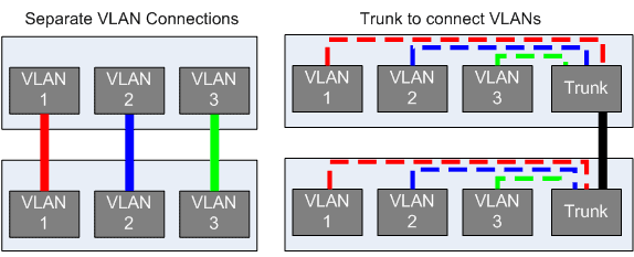
Figure 0.2: Using many cables vs. a VLAN trunk
Fortunately, there is a way to enable one connection between devices to be able to carry the traffic of multiple VLANs. It’s called trunking, and is displayed in Figure 0.2. Trunking utilizes a technique known as VLAN tagging, where each packet of data has an identifier added to it which indicates the VLAN to which it belongs. To take advantage of trunking, we need to configure the switch port that has the cable connected to the other switch as belonging to all of the VLANs, and we do it on both switches. At this time, we’ve also got to ensure that both switches are set to the same VLAN tagging scheme. The most pervasive standard is 802.1q, known colloquially as dot1q.
Routers
Just as a switch creates more network segments, a router creates more broadcast domains. A router’s job is to accept packets and forward them to their destination, as determined by the layer 3 IP address. Because they function as traffic control, they are in an excellent position on the network to perform as a firewall, which limits or permits traffic based on a rule set. Many vendors have created Unified Threat Management (UTM) devices that function as a router, firewall, and in-line virus scanner all at once, but even the most basic routers have rudimentary firewalls in the form of Access Control Lists (ACLs). Since routers operate at layer 3, and make decisions based on IP addresses, it’s necessary to understand how IP addresses are calculated in order to really understand how routers work.
IP Addresses and Subnets
IP addresses (sometimes referred to as IPs) are layer 3 addresses. IPv4 addresses consist of 32 bits of information, typically expressed as a series of four decimal numbers between 0 and 255, inclusive. A typical IP address for a Small Office / Home Office (SOHO) router might be 192.168.1.1, for instance.
Each IP address also has a subnet mask. The subnet mask is a 32 bit string of ones and zeros, usually converted to decimal, although sometimes expressed as a slash followed by the number of ones contained within the subnet mask. A common subnet mask is 255.255.255.0. When 255 is converted to binary, the result is 11111111. As you can see in Figure 0.3, 255.255.255.0 converted to binary consists of 24 ones, followed by 8 zeros. This subnet mask can be expressed as /24. This is known as Classless InterDomain Routing (CIDR) notation.
Every IP address belongs to a specific range, called a subnet. The subnet that an IP belongs to is determined by performing a bitwise-AND operation of the IP address against the subnet mask. In other words, by comparing the binary representation of the IP address to the binary representation of the subnet mask, we can find out to which network the IP belongs.
As we can also see in Figure 0.3, an IP address consists of a network portion and a host portion. When the binary bits of the host portion are all set to zero, the resulting IP address is known as the “network address”, which (when coupled with the subnet mask) refers to the network itself. When the host portion bits are all set to one, the resulting IP address is known as the broadcast address. Any traffic sent to this address will be broadcast to all hosts on the subnet.
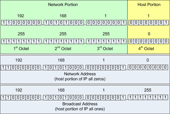
Figure 0.3: IP address and subnet mask with binary equivalent
Devices can only communicate with other nodes on the same subnet. In order for two subnets to communicate, a router must be placed between them, such that it has interfaces on both subnets. The router recognizes layer 3 source and destination addresses, and forwards packets between the subnets as appropriate.
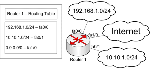
Figure 0.4: Router with three interfaces, labeled fa0/0, fa0/1, and fa1/0
The typical small infrastructure router deals only in static routes, where specific instructions are given for every network that the router knows about, and all others are sent out the “default route”. The router shown in Figure 0.4 exists in a small computer shop. There’s an external network for customers (the 192.168.1.0/24) to connect their computers being repaired, and there’s an internal network (10.10.1.0/24) for the shop’s internal machines. The router only needs to remember that 192.168.1.0/24 is on the fa0/0 interface, 10.10.1.0/24 is on the fa0/1 interface, and anything else is out the fa1/0 interface.
The network in Figure 0.4 is situated in this manor to prevent the computer shop’s machines from communicating with potentially compromised computers that the customers bring in. By separating them with a router (capable of acting as a firewall), much of the potential damage is averted.
When we obtain a connection from our internet service provider (ISP), we are typically given an IP address, or a block of IP addresses. These addresses are publically routable, meaning everyone on the internet can reach those addresses. They’re very useful whenever we want to provide services over the internet, and even if we don’t, our gateway device through which we get internet access needs to have one of these addresses.
It is often the case, though, that we wish to use more IP addresses than we’ve been given, and frequently it is attractive to use IP addresses that are not available to the internet at large. For this, we create a network with IP addresses from one of the private address pools. We’re almost all familiar with some of these addresses already. Almost all home routers assign IP addresses in the 192.168.1.0/24 range, or something similar. Two of these address blocks are used in Figure 0.4.
Private IP Addresses
10.0.0.0 – 10.255.255.255 (10/8 prefix)
172.16.0.0 – 172.31.255.255 (172.16/12 prefix)
192.168.0.0 – 192.168.255.255 (192.168/16 prefix)
RFC 1918 – Address Allocation for Private Internets
The private IP blocks are dictated in a document named RFC 1918.
The text of this document can be found at http://www.faqs.org/rfcs/rfc1918.html.
As computer networks multiply, the need to keep track of more subnets make static routes unwieldy. To facilitate further network growth, routing protocols have been designed to efficiently keep track of the network topology so that information can be routed correctly.
Most small infrastructures don’t need to implement these protocols, with the possible exception of the Border Gateway Protocol (BGP), which is used by some network providers to route traffic to end users. In that case, the providers should give instructions, and have engineers available to offer advice and assistance.
This document contains proprietary information and is protected by copyright law.
Copyright © 2026 Red Gate Software Limited. All rights reserved
Load comments