
At its core, the physical aspect of computer networking really deals with two types of things. There are devices, which utilize or facilitate the network, and there is the medium between those devices. There are wide arrays of both, and each has an entire ecosystem of products meant to assist their installation, operation, and removal.
Each vendor has their own product lines, and each product line has its own model numbers, feature sets, and pricing scheme. While some model names and numbers are easily understood, others read like hieroglyphics.
It isn’t difficult to be confused when dealing with a new line of equipment. The best tactic we can use when looking for a particular feature set, or if we’ve got a question about a particular model, is to ask. Call the vendor (or a retailer who carries products from that vendor), and learn from the source. There’s no shame in not knowing the feature set on someone else’s equipment, and asking someone who knows is the best way to gain the knowledge. Often the vendor or reseller can point us to the resources that clarify feature sets and provide necessary statistics.
This article is not a comprehensive guide to physical networking. It will attempt to clarify how the hardware out there can best be selected and put to use in our infrastructures. We’re also going to look at the media connecting these devices, and the tools we can use to troubleshoot problems.
Having a solid design for our network is only half of the battle. The physical layout of the network needs to be done right, too, and being done right means using the right techniques and making the most of our resources.
Cabling
Whenever we deal with physical networking, cables are a part of life. Cable management can be as complex as we want to make it, and it seems like there’s always something else that can be done to improve the infrastructure.
So many of the techniques for running and maintaining the cables are in direct response to the composition and structure of the cables themselves that it would be wise to review how cables themselves work.
Wiring Concepts
The concept of sending electricity over wires is not new. The first electrical transmission of signals for communication happened in the early 19th century using the electrochemical telegraph. Since that time, we have advanced drastically, but transmitting electricity over metallic wires is the same as ever, whether for the telegraph or Ethernet.
Copper Wire
In a wire, electricity flows through a conductive material from one device to another. As it does so, it produces a slight magnetic field and some degree of electrical noise, similar to a radio antenna. The signal in the wire is also susceptible to outside radio noise. When that external interference is caused by other wires in the immediate vicinity, we refer to the effect as crosstalk.
Partially because of this bleed off of signal, wires are subject to attenuation, meaning that their signal becomes weaker as the length of the cable increases. This limits the maximum usable length of metallic cables. Techniques have been developed to limit the attenuation suffered by cables, and the most widely utilized technique is to take a pair of wires and wrap them around each other. This technique is known as twisted-pair, and nearly every copper networking cable uses it.
Copper cable can be either stranded or solid, with different applications for both. Stranded copper cabling has many very fine copper wires, whereas solid has one large conductor. Stranded wire is more flexible than solid core, and is more frequently used in situations where cables are frequently moved or adjusted. Stranded is less expensive as well, although solid core theoretically provides a better throughput.
Because of the susceptibility of networking cables to accept interference, particularly from electrical power lines, whenever network cables need to be run through an exceptionally noisy area, a special type of network cable can be used. The normal twisted pairs are wrapped in a metallic foil which has been grounded on both ends. This has the effect of dampening any external electrical noise which may have otherwise interfered with the signals on the network. These cables are referred to as Shielded Twisted Pair, or STP. It’s used rarely, and only in environments which otherwise are unable to use Unshielded Twisted Pair (UTP), as the more common network cable is known. The reason it isn’t used as frequently as UTP is the additional expense of the metallic shielding, the extra work of grounding it at each end, and also because if installed improperly, the entire length of shielding can serve as an antenna, effectively doing more harm than good.
Most of the networking cable in the world is classified as either Category 5 (Cat-5) or Category 5 enhanced (Cat-5e), both of which are capable of up to gigabit speeds. Most new installations specify Category 6 (Cat-6) cable, which provides better insulation from cross talk, and also supports gigabit speed, but is designed to lower latency. Both Cat-5(e) and Cat-6 can be either UTP or STP, but UTP is far more common.
The difference between Cat5 and Cat5e
Upon casual inspection, cable labeled Cat5 and cable labeled Cat5e appear identical. Both have 8 wires consisting of 4 twisted pairs of matching color, however the difference becomes apparent over distance. The twisting of the wires is what protects the data integrity as it traverses the cable. Cat5e has a higher twist frequency than Cat5, and as such the signal degradation is less intense over a longer length of cable.
Both Cat-5(e) and Cat-6 cables consist of eight wires arranged in four pairs. The pairs are differentiated by being color matched, with one pair member being a solid color and its partner being white with a colored stripe. For instance, a color pair could be orange and orange/white. The colors are orange, green, blue, and brown, and in computer networking, only the orange and green pairs carry signal.
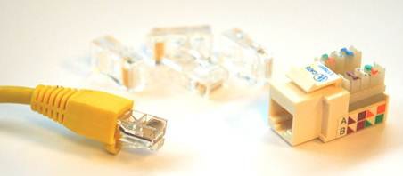
Cat-5&6 are typically terminated using an 8 Position 8 Contact (8P8C) ends, commonly called RJ-45. These plastic ends have metal teeth that, when crimped down, bite through the insulation and into the copper core. It’s important to pay attention to whether the cable we’re crimping is stranded or solid core, as each requires a specific RJ-45 end, although there are general purpose jacks which can terminate either type of cable.
Copper cable is effective for many situations, but the overall length is limited, due to attenuation. Because of that, and due to eventual bandwidth limitations, other cabling mediums had to be devised.
Fiber Optical Cable
The maximum usable length of a UTP cable is 100 meters. Fiber optic cable is necessary for cable runs exceeding this length. If the distance is around a kilometer or less, multimode fiber can be used, and if longer, then single mode fiber is necessary.
Multimode fiber is made of very thin strings of high quality clear plastic encased in thin plastic sheathing, which is then encased in rubber. These optical cables are frequently used for high speed long distance runs inside of buildings between important network points. The light source for multimode fiber is LED-based, and this, along with the tendency of even the highest quality plastic to absorb light, limits the length of these cables. The real determining factor in the distance is the transceiver, but in general, 1km+ runs are possible if slower speeds are acceptable. For higher speed or longer runs, single mode fiber is necessary.
Single mode fiber is extruded glass which is then sheathed in Kevlar, the same material used in bullet proof vests. After this shielding, several layers of plastic and rubber are added to protect the fiber and limit its bend radius. Single mode fiber is typically used in Metropolitan Area Networks (MANs) and inter-city links. A single mode transceiver uses a laser, rather than the comparatively weak LED, which combined with the clearer transmission of glass rather than plastic, leads to the ability to push the light several kilometers without refreshing the signal through the use of repeaters.
The main drawback of fiber optic networking is the cost involved. Fiber cables are more expensive than their copper counterparts, as are fiber transceivers. The cables are more fragile, as well. Every cable, copper and fiber, has a bend radius, which is essentially the radius of the smallest pipe that they can safely be curled around. The bend radius of a typical Category 5 Ethernet cable is around 1 inch, meaning it can be safely curled into rings two inches across. A typical multimode fiber optic cable requires a much larger radius, even though it’s made of relatively flexible plastic. A Kevlar-sheathed glass cable is even less flexible, requiring comparatively huge radii. It’s important to keep bend radius in mind when runs through a building are planned.
Wireless
As it turns out, the electromagnetic radiation emanating from cables can be put to good use. Radio waves have carried analog signals for years over AM, FM, and television frequencies, but only recently have radio waves been used to transmit binary data. Off the shelf wireless technology for use at home and business takes place over a few select bands of the electromagnetic spectrum that have been set aside for public use in the U.S. and U.K. among others.
The Institute of Electrical and Electronics Engineers (IEEE) established a standard for wireless LAN known as 802.11. Subsequent modifications to this standard are noted with a letter appended at the end of the designation, such as 802.11a.
The most popular standard is still, as of this writing, 802.11b. This standard operates at 2.4ghz, and 11Mb/s speeds are theoretically possible, although in practice the throughput is considerably less. 802.11g, another update to the standard, and still at 2.4ghz, was a commercial success and offered a theoretical maximum of 54Mb/s. The most recent addition, as of this writing, is 802.11n. It promises speeds approaching wired LANs, at 600Mb/s (theoretical) and utilizes either 5ghz or 2.4ghz, depending on the configuration as well as other wireless signals within the same area.
It’s important to remember that 2.4ghz is an unlicensed frequency, and as such, other devices in the vicinity may utilize it. Microwaves are a well-known source of wireless interference, for instance.
Microwaves and wireless
It is a widely-believed myth that microwaves cook food by heating water to its resonant frequency, 2.4ghz, which, according to the urban legend, causes the water to absorb radio waves. In fact, microwaves cook food by dielectric heating, where water molecules twist back and forth, bumping into each other. This causes the heating, not the absorption of radio waves. This effect takes place over a range of frequencies, and 2.4ghz is only one of them. The cooking effect, called diathermy, also happens to your hand if you place it in front of a powerful enough radio transmitter. This should be reason enough not to stand in front of satellite dishes.
Building Layout
When running network cable, we are at the mercy of the environment through which our cable needs to traverse. The cable length, composition, and cladding are all dictated by the locations in which we need to install it. With that in mind, we should be familiar with the most common types of installation site, which is an office building, factory, or warehouse.
Generally, when commercial or industrial buildings are designed, a location is designated to function specifically as the site where utilities such as electricity and telephones enter the building. In this room, punch down blocks are typically used to transition from the provider’s lines to the building’s built-in wiring, also known as “house wiring”.
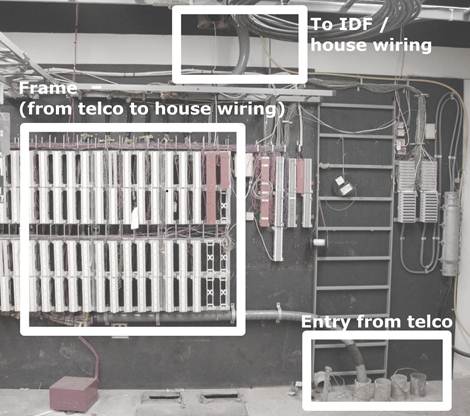
In small buildings, this is a wiring closet, or sometimes the facilities room. In larger installations such as those in multi-tenant office buildings, it is known as the main distribution frame, or MDF. We might sometimes hear the MDF referred to as the demarcation point (or just demarc), although technically the demarc is simply the point where the handoff between the provider’s network and our network begins. The demarc is typically located in the building’s MDF, but it doesn’t have to be. On occasion, a provider will extend the demarc into a server room or wiring closet.
Depending on the building size, there may be additional spaces on other floors (or even the same floor, if the area is large) to which wiring is run from the MDF to allow for local distribution to endpoints. These additional spaces are considered Intermediate Distribution Frames, or IDFs.
When one organization has multiple distribution frames, the cables between them are collectively called the backbone, and are typically as high bandwidth and low latency as can be afforded.
Many small infrastructures inhabit a leased space in a larger building. Typically, services such as telephones and internet will be delivered through the MDF to the IDF nearest to the network, however it may be possible to have the provider install directly into the leased space. In this case, the building physical plant team should be consulted to ensure that this complies with lease agreements and the like.
Tools and Parts
Theoretically, the space in which our business is housed could have enough good-quality network cable installed to be sufficient. I say theoretically, because I’ve never personally seen it or heard of it. Additional network cable is nearly always required, either because our company has grown and we need more runs, or because the existing cable (if any!) wasn’t installed to a particular space that is now needed, or even because instead of something reasonable like Cat5, the people who had the space before us were Neanderthals who used coaxial thicknet cable, and we want to advance to technology used in the latter half of the 20th century.
Network wiring in new buildings
As backwards as it seems, there are some times when the network cabling in a new building is more unusable than in an older structure. Many construction companies outsource the wiring work to electrical contractors, and often, the network cable is lumped in with the power lines. There are many tales of electricians who were unfamiliar with network cable and used incorrect installation methods. I have heard tell of long network runs parallel with electrical lines, and even stapling Cat5 to the wall is not unheard of. In a new install, make sure to check the quality of the network drops before you rely on them.
If we’re fortunate, we may be able to have contractors do a professional cable installation of the lines we need. If the install job is too extensive for one person, or it would exceed our available resources to complete the job in the required time, then bringing in a contractor is our only option.
Running Cable
Let’s assume that we’ve got to run the network cable ourselves. Suppose we’re running four cables from the wiring closet to a sales office. In the wiring closet, there’s already a hole in the wall that existing cable is being run through, but we’re going to need to punch a hole in the drywall in the office. We’re fortunate, because the office has a drop ceiling, which makes wiring much easier than ceilings that are plastered, paneled, or otherwise closed off. The ability to remove tiles to guide the run speeds things up and reduces guesswork.
The overview of the cable running process is that we will first flip off the breaker for the rooms we’re working on, then prepare the walls at each end of the cable, plan the network run, prepare any hardware needed to facilitate the cables, run the cables, terminate the cables at each end, then test the runs.
Despite the relative ease that our office configuration affords, certain tools and parts will still be necessary to do the job correctly.
Stud Finder
A normal drywall installation consists of a sheet of gypsum board nailed to a framework of vertical slats. These slats are called studs, and they are arranged in regular intervals across a wall. The network jack should be installed between the studs.
Because they’re impossible to see once the drywall has been installed, a stud finder is used to locate the vertical beams. The stud finder works by sensing the relative density of the beam versus the empty space. Place the stud finder against the wall in between the studs, and nothing happens. Slide it across the wall until you get to a stud, and the lamp lights, or a tone is emitted.
Stud finders are sold in hardware stores that carry carpentry equipment or home improvement tools.
Measuring Tape
Network and power receptacles shouldn’t be installed at the very bottom of the wall. Cables can be tripped over, kicked out, and damaged by any number of things.
It’s a better idea to keep them at a specific height from the floor (and in some cases, it may be codified by law. We should check our local regulations to be sure). Uniformity looks professional, so rather than just guessing at the height, we’ll use a tape measure to guarantee the height of the holes for our network jacks.
Level
Since we’re doing a professional job, the network jacks should be installed so that they’re straight, in respect to the walls and floor. In most buildings, the walls are perpendicular to the floor, and the floor is level to the ground. Use the level to ensure that the network box is, too.
Work Boxes
After we’ve cut a hole into the drywall, we need to make the hole ready to hold the jacks that we’ll be using. In order to do that, we need to use work boxes.
Work boxes are rigid square or rectangular boxes that mount into the wall and support a certain number of modules. These work boxes are mandatory for electrical work, such as light switches and electrical plugs, and are handy for telecom, as well.
Typically composed of metal or plastic, they come in full-box form (required for electric), or just as a frame, for low voltage work, which is what our network installation will be. In the store, they come in two varieties, new work and old work.
New work boxes are used when a workspace is being built. During the construction process, the walls are still open to the studs, and the drywall hasn’t been nailed on yet. At this time, we have full access to the studs, so we can use a “new work” box, which utilizes long nails which are driven diagonally into the studs to secure the box.
If we’re renovating an existing space, as we are in this example, we don’t have unrestricted access to the studs, so we’ll use an “old work” box. Instead of nails driven diagonally, these boxes have flaps which open and spread out behind the drywall. Once they’re opened, screws on the front of the box are tightened which cause the flaps to squeeze the drywall. This secures the box against movement without needing to remove extra drywall.
Drywall Saw
Since drywall is compressed gypsum powder covered with a thin paper, it isn’t difficult to saw through. In fact, a utility knife can be used to cut through drywall in a pinch, but I prefer to use a drywall saw. These saws are very sharp, and feature large serrated blades, designed to remove gypsum quickly.
Safety and Construction
Before we make the first cut into the wall, we need to make sure that the breakers for the circuits in the room we are working on are flipped off. Cutting through a live circuit is an effective way to get badly hurt and possibly killed. It wouldn’t be overkill to include an outlet tester in our kit to ensure that the circuits we’ve flipped off are connected to the outlets we thought they were.
Eye and Lung Protection
Drywall being sawed kicks up a lot of particulate matter. Good eye protection is a must, and safety glasses are cheap and effective. I also use them whenever I deal with drop ceilings, since the ceiling tiles are invariably dusty and fall apart. At the same time, when sawing through drywall, a simple particulate mask should be used. Gypsum dust exposed to the moisture in our lungs forms an excellent cement. It would be best to prevent this.
Fish Tape / Rods
Getting the cable from one end of the run to the other would be easy if the entire route were exposed. Unfortunately, this isn’t usually the case, and so the wire has to be able to be placed through openings smaller than we, ourselves, could fit in. Even this wouldn’t be impossible if the network cable were rigid, but as it is, we can’t push them the entire way.
To get around this issue, we use fish tape to pull network cabling in places we can’t install it directly. Fish tape is a somewhat rigid wire, typically made of spring steel or fiberglass, which has been coiled in a convenient case. The exposed end of the wire has a loop that we can secure to an end of network cable.
The way to use fish tape is to push (otherwise known as fish) it from one end of a run to the other while it’s empty, then once the tape is at the target, attach the cables and pull-strings to it, and then reel it back in, which pulls the cables into place at the same time.
Fish tape works best in a relatively straight run, or one which makes a single ninety degree bend. In many cases, we’ll need to use the fish tape multiple times over the course of the run.
In the case of our installation, we can use the fish tape to get the network cables up the wall and through the route in the ceiling that we need them to take. Because there are multiple bends in this run, we’ll need to take it in stages.
We’re terminating the wire runs from the wall into a patch panel in the server room, and it is always good to leave a bit of extra cable near the termination point, so we’ll start the cable from the wall outlet to make it easier to leave extra cable on the patch panel end of the run.
Since the fish tape should only make a single sharp bend at one time, we can’t just fish the tape from the patch panel to the wall outlet. This means that we’ve got to start our fish tape from the next logical step.
To start off, we’ll take our fish tape reel, grab a ladder, and open the ceiling tiles. While we’re up on the ladder, we should take advantage of our view and check out the general status of the ceiling space (also called the plenum space). Are there old cables, signs of infestation, or anything else that looks unusual? The area should look relatively dusty, but uncluttered. The presence of things that don’t belong there might indicate the presence of pests, and should be further evaluated by a professional exterminator.
We also need to check the path that we’re going to be fishing the tape through. In-ceiling fixtures like duct work and full-height walls will provide challenges for us, and we need to plan a route around these before we start fishing cable.
Assuming we’ve got our path planned, we’ll feed the fish tape toward the wall with the hole for the jack cut into it. A straight line is better than one that weaves, and we should try to keep the network cable’s path at right angles to the in-ceiling power cables that snake through and run fluorescent lights.
Once the tape has been fished to the wall, it’ll probably be necessary to leave the reel in the ceiling while we go to the wall and feed the far end down between the beams that form the studs. If there’s a horizontal beam sealing the top of the wall, a drill with a hole-saw bit will give us the access that we need.
Once the tape end is being fed into the wall itself, feed some more line out to make sure the end is able to reach the hole cut for the jacks. Returning to the wall, it should be possible to extract the tape end. Once we’ve done this, we can attach the cables to the loop at the end of the fish tape.
After the cables and pull string (see next section) are attached to the fish tape, go back to the ladder, retrieve the spool, and pull the bundle to yourself. Once the cables are to you, detach them from the fish tape, and move the tape (and your ladder) to the next spot, which in our case is the panel itself in the server room, where we’ll fish the tape back through to the midpoint where our bundle of cables is left.
Creating a large ball of wire by directly attaching all of the cables to the fish tape itself would make an unmanageable mess while trying to pull the cables back through the run. Instead, we need to tape one wire to the tape itself, wrapping it around the hook at the tip, we should use electrical tape to fasten it so that it doesn’t come loose. If we need to attach more cables, we should tape them to the initial cable. As we add more cables to this run, we need to add some space between their ends, to prevent the aforementioned bunching up.
Running Multiple Cables at Once
Something that it’s important to remember when planning this phase of the cable run is that, in order to run multiple cables at once, multiple cable sources are needed. In the case of network cable, this will be one spool or box of cable for each wire being run. It sounds like common sense until you forget to account for it.
It’s possible to hook several network cables to the fish tape, but for larger bundles, it’s better to tie pull string to the tape, because we can then pull as large of a bundle as we need.
Pull String
Suppose that we have large amount of network cables to run, around a dozen. We could do as we did above, and tape the first cable to the tape end, then attach the other eleven cables to the first, with some amount of distance between the ends. By the time you got the last cable on, you are pulling a significant amount of weight with a thin, flexible metallic (or fiberglass) wire, and there’s over a foot between the end of the first cable on the end of the fish tape and the last, taped onto the bunch.
Instead of doing this, we can use pull string (also known as pull cord) to put less tension on the fish tape, and to pull nearly unlimited cables.
Pull string is a very soft, very strong nylon rope. It’s typically sold in buckets measured in thousands of feet of length. This lightweight rope can be used in lieu of taping dozens of cables together. Rather than attaching network cable directly to the fish tape end, we secure the nylon pull string to the fish tape using a knot, then pull the string through just as we would the network cable bundle. After the pull string run is complete, we’re free to go back to the hole in the wall, make a cut in the pull string, and then tie it around the bundle of network cable that we need to run.
It’s important to maintain the staggering of the cable ends, but a much larger number of cables can be attached. The method that I recommend is to bundle the cables together using tape as described above, then wrap the pull cord around the entire bundle, then use liberal amounts of electrical tape to ensure that the cord doesn’t pull lose. This method creates a strong bond and helps ensure that none of the cables are lost during the run.
Whichever method we employ, it’s always smart to include pull string in with the bundle of network cables. This allows us to pull additional cables in the future without breaking out the fish tape. By guaranteeing that each cable run has a pull string, future expansion and upgrades are made much easier.
Punch Down Tool
Once the cable is completely run from the wall to the patch panel, it needs terminated at both ends. Permanent wiring needs to be installed such that patch cables can be used at each end to connect to hosts or networking equipment. To permit this, we need to use female receptacles which the patch cables can plug into. For cables near end users, wall plates featuring 8C8P (or RJ-45) ports. These wall plates are the same size as those made for electrical outlets, but feature square holes for clip-in female RJ-45 jacks.
These female ports have metal contacts on the reverse side into which the individual wires can be pushed down. These metal contacts are in thin plastic slits, and are shaped such that they cut into the insulation of the wire and allow connectivity. In order for the wires to be forced into the slit, a special device is used. The punch down tool pushes the wires into the slits. In more expensive models, this action also cocks a gear, much like a gun, which, when released, slices off the wire which extended beyond the punch down block. When wiring to punch down blocks, ensure that the twists in the cable pairs are maintained as close as possible to the ends of the wires. These techniques eliminate additional cross talk.
Punch down tools are available from many sources. Nearly all hardware stores that carry telecom equipment sell them. Most of the RJ-45 jacks that are sold come with extremely cheap versions that do more pushing down than punching down, but in a pinch, they’re better than nothing. If we’re stuck using these, we need to make sure that we take a box cutter or razor blade and remove the extra wire length. This gives the best, cleanest signal.
Crimpers
As mentioned before, permanent installations should be terminated in jacks, either in-wall or to patch panels. The connection from these jacks and panels to the actual machines should be accomplished using patch cables with male 8C8P (RJ-45) ends.
These cables are commonly sold almost everywhere now, but online bulk retailers typically have the best deals. Although I recommend buying them for everything important, they’re simple to make. The only hardware needed is a pair of scissors, the plastic ends, the cable itself, and a pair of crimpers.
The plastic ends into which we put the wires are built such that the metal contacts on the outside are able to be pushed down into the copper core. Because there are both stranded and solid core wires and ends made for each, we should make sure that the end we’re using is made for the wire type we’re crimping it on.
Crimpers come in a range of sizes and capabilities. Personally, I stay away from both extremes. The most inexpensive always feel cheaply made, and are sometimes made of plastic. On the other hand, the high-end crimpers have far more features than I would utilize, support more cable types than I need, and are way too expensive. Instead, I go with a moderately priced pair of crimpers which are metal, somewhat heavy, and are ratcheted, which means if my hand slips mid-crimp, there’s still a good chance that the end won’t be ruined; if my hand slips on non-ratcheted crimpers, I’m almost guaranteed to need to cut off the end and do it again.
To prepare a cable for crimping, use a pair of scissors to lightly score the external sheathing an inch or so away from the end of the cable. It’s important not to score the cable so hard that we cut through sheathing and into the wires themselves. After the pairs are exposed, we need to untwist them and flatten them out as best we can. At this point, we can start arranging them in the proper order for the cable we’re making.
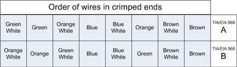
Copper Cable Standards
For CAT-5, the color order and composition of the individual wires are dictated by a standard known as TIA/EIA-568. There are numerous revisions to this standard, denoted with the A, B, C.0, C.1, and C.2 monikers, although only A, B, and C.2 deal with copper cables such as CAT-5e. A and B each dictate the order of the individual wires within the cable ends. The only difference between A and B are that the orange and green wires are reversed.
Once the wires are arranged into the proper order, we need to pinch them between the thumb and first finger, while using the scissors to swiftly cut them a quarter inch from the sheathing, and at a right angle. This should leave a clean square cut. Without shifting our fingers whatsoever, slide the plastic end onto the wires pressing down firmly on the wire tips. The purpose behind this is to ensure that the wires don’t move in the slightest, because even a small shift can cause the wire order to be changed, which ruins the cable.
Slide the plastic end on, and press firmly. The best way to make sure that the end is solidly on the wires is look directly at the tip to verify that we can see the eight individual shiny wire ends. If we can’t, the end is more likely to test wrong, because the metal teeth may not penetrate fully into the copper core.
Once the plastic end is secure on the cable, with the wires in place, shove the end and cable into the crimper port, and look again at the tip of the plastic end to ensure that the copper wires are showing. Assuming that they are, squeeze firmly until the crimpers won’t move any further. Releasing should open the crimpers, and the cable can be removed.
Cable Testers
Even the best crimper out there will make mistakes. No matter how nicely the cable run goes, it’s possible to snag it on something and break one of the internal wires. Many times, it isn’t apparent that there’s a problem, even when inspecting the cable. In order to tell that there is an issue, the electrical properties of the wires themselves must be tested.
Cable testers come in all shapes, sizes, and costs. They range from simple continuity testers to multi-thousand dollar units that report on every aspect of the wire.
Most cable testers have a base unit, which is where the active electronics are stored, and a smaller remote unit, which plugs into the far end of the line. This remote unit communicates with the base unit to report statistics and performance data.
The preferred wire testers will do continuity, plus report the order of the wires, and in the event of a problem with the cable, will report the distance from the end that the cable is damaged. The bare minimum we should look for in a cable tester is the ability to report crossed wires. It’s easy for a miscrimp or mispunch to ruin a cable’s ability to carry data, and without a cable tester, debugging that particular problem would take a long time.
If possible, try to get one that will report supported bit rate. This data is important in debugging network performance problems. We’ll never get gigabit speed if our cables can’t even support 100Mb/s.
In addition to testers that certify cable, tone generators are very useful. The idea of a tone generator is that one end of the cable is plugged into the device which generates an identifiable signal. Another device, the detector, or wand, is used to identify the specific cable in a bundle remotely from the generator. Touching the wand’s end against the specific cable generates a tone, alerting the user that they have found the proper cable.
These devices are invaluable whenever a problem exists mid-run, or when mapping out an undocumented installation. Two people can make quick work of a relatively complex installation, and even one person can do the job given enough time.
Networking Devices
Networks exist to move information from one host to another. We use networking devices to facilitate this flow of data, and many types of devices are used to propagate the traffic to its destination.
Networking devices are loosely arranged in tiers which correspond to build quality, feature set, price, and manufacturer support. The range of hardware between home and enterprise is frequently called Small Office / Home Office (SOHO) or Small / Medium Business (SMB) (sometimes called Small / Medium Enterprise, or SME).
Small infrastructures don’t usually have a lot of financial resources, and we can’t afford to waste money by buying the wrong equipment, or worse, unreliable equipment that we’re going to have to replace too soon. For these reasons, the value and reliability of our hardware should be paramount.
Don’t confuse price with value
There are a great many inexpensive pieces of computer equipment that could be given to us for free, yet would still be too expensive to use on our network. Everything has a cost, even if it’s not tangible. Spending time to configure equipment costs money, since our efforts aren’t free. So, too, does downtime, because infrastructure operations may hinge upon unreliable hardware or software. At the same time, many “free” solutions are better in nearly every way than expensive supported solutions. Investigate everything, and don’t be afraid to beat the bushes to find people who have worked on the solution before.
I’ve often had a difficult time finding reliability statistics (or even estimates) for SOHO equipment. The applicable term to look for when evaluating hardware is failure rate, although it is more common to see Mean Time Between Failures (MTBF) quoted. This metric is the mean average of time a device operates correctly between failures. Of course, this being statistics, there is no guarantee that this time span will be borne out in our equipment, but it does give a good indication of the reliability of the hardware being purchased.
Reliability and Mean Time Between Failure
Devices primarily fail when they are very new or very old. Between those times, the failure rate is relatively consistent, and MTBF is drawn from this consistent rate. It should be expressed in machine-hours per failure or failures per machine year. Without an expression of a unit of scale, such as hour or year, the number is worthless. See http://www.faqs.org/faqs/arch-storage/part2/section-151.html for more details.
Hardware Taxonomy
Network devices can be divided into two general families. There are distribution devices, which connect end-nodes to the network, and there are transit devices, which allow, deny, or otherwise alter the flow of network traffic through connected networks.
Distribution Devices
Hubs / Repeaters / Taps
Hubs and repeaters were among the first networking devices, and their operation is simple. They take all of the bits that enter a port and retransmit them out all of the other ports. Early in network computing, they were considered an asset because they increased the number of connections to the network, but with drawbacks such as the extension of a shared collision domain, there are much better solutions now. In the real world, a lot of small shops still use hubs. If we’ve got one in our network, it should be on the top of the list to be replaced. If we need a new distribution device, it doesn’t matter how cheap a hub is, it’s still too expensive, because the performance losses are immense.
There is one exception to the “no hub” rule. If we are implementing a Network Intrusion Detection System (NIDS) then a small hub can be a simple way to monitor the traffic to a single node. Aside from this usage, it is in our best interest to keep hubs off of our networks.
Network taps are related to this single use case for hubs. A network tap is essentially an extension of the cable connecting a host and a switch. Taps are either active or passive, and exist for both copper and optical cables. Passive taps are generally seen as the more reliable of the two, but often lack administrative abilities.
Switches
Switches are the work horse of the network. Every one of our wired nodes will be connected to a switch, and they play an important role in the implementation of our network.
There are two major varieties of switches, managed and unmanaged. Unmanaged are the generally the less expensive of the two, but have no configuration options whatsoever. We should try to avoid these, if at all possible. They are usually of lower quality than managed, as well, and eliminate our ability to perform vital monitoring of the network resources.
Instead, we should try to buy managed switches. These include an additional controller inside the switch that allows us to set an IP address and log in, typically via serial console, web, or telnet. Typically, managed switches support Simple Network Management Protocol (SNMP), which allows us to view port status, counters, and in some cases, alter the configuration of the switch.
Managed switches can be small, as small as 4 or 5 ports, or very, very large, including hundreds of ports housed in a tower the size of a small refrigerator. Typically, switches with more than 12 ports are in a 19″ rack mount chassis, as seen in Figure 2.1. This allows the switch to be mounted as part of a server rack installation, allowing optimum cable management and efficiency when networking servers or wall jacks.
Smaller switches usually have a fixed number of ports, until you get above 48 or so. After that, switch chassis typically accept blades full of ports, which allows an organization to grow as needed.
These smaller switches are sometimes stackable, which means that they can be connected such that together, they function as one single switch. The benefit of this is that all of the switches together may be less expensive than the equivalent large chassis switch. The drawbacks are that the bandwidth between the switches is somewhat limited, compared to the backplane of the larger chassis switch, and failure rates increase as the number of individual components go up.
Larger switches are sometimes capable of handling add-in cards which provide some amount of routing capability. Effectively, this makes them “Layer 3” switches. Although these cards aren’t typically capable of dealing with as much routed traffic as a dedicated piece of hardware, these features can be used to our advantage if we have the budget for this class of hardware.
Another feature of switches which is becoming very important is Power over Ethernet (PoE). This feature enables the switch to power compatible network devices at the other end of the network cable, through the cable. This is particularly handy whenever we need remote network connectivity in a spot where there may not be a readily available power source, such as when we install wireless APs and security cameras.
Which Switch?
There is no “best switch” or even “best class” of switches. Each site’s requirements are too different for any one standard. Instead, we need to look for switches that mesh with our existing infrastructure, or with the infrastructure that we’re building. The requirements for our network topology play a large part in dictating the feature sets we require in our routers.
When it comes to selecting the size of your switch, your options are determined by the number of ports available and the speed at which they run. There are some considerations to be made, because as the number of ports increase, the cost goes up accordingly. With that in mind, it is usually more expensive to purchase a second switch than to purchase a switch with room for growth.
There was a time not so long ago where every single host on your network needed its own network cable. Because of virtualization, that’s not necessarily true any longer. Not every infrastructure has implemented virtualization, but more and more are migrating to it. Small infrastructures are going to be among the last, because the comparative value is smaller for us, although there is still a value. One of the side effects of adopting this technology will be that the relative size of our server switches can be smaller, and the growth pattern of machines on the network may not be reflected physically. In the end, it’s just one of the many ways that virtualization can save money. If multiple machines can share the same network cable, that’s good, because big switches are expensive.
Network growth has been matched by the size of the data needing ferried about the network. To accommodate this trend, port speeds have steadily increased. As of this writing, gigabit speeds are common, and 10GB is on the horizon, although primarily targeted at Storage Area Networks (SANs).
Although common, high performance managed gigabit switches are still relatively expensive. The previous generation of 100Mb/s switches are very affordable and still quite adequate for end-users in many instances.
One of the relatively recent features that is appealing to administrators is Power over Ethernet (PoE). This technology uses the brown/brown-white pair to transmit electricity through the Ethernet cable, which is then used to power the remote device. While the technology isn’t typically used to power computers themselves, it does go a long way toward simplifying the installation of wireless APs, cameras, and other remotely-installed network devices.
Each site will have its own peculiarities and requirements, and deciding on the right switch will require analyzing the infrastructure and the prices available at that time.
Wireless Access Points
The term access point (AP) is not a misnomer, but the term doesn’t speak to what function the device really provides. A wireless AP is really a wireless switch. There are some particular configuration options and specific security concerns, both due to the networking medium, but essentially, the AP performs the same logical function, which is connecting end nodes to network resources.
Wireless networking is a layer 1 technology. The radio waves take the place of network cables, and as mentioned above, this introduces some very important security considerations. We wouldn’t wire up the outside of our building with RJ-45 jacks so that anyone could connect to your network, yet that’s effectively what wireless does. It’s for this reason that a great many security controls have been put into place to specify who is able to connect and how.
When we shop around for an AP, the two most important features to look for are speed and security options. Wireless technology is constantly getting faster, with current maximum speeds on consumer hardware reaching a bit over 100Mb/s. The equipment has, thus far, remained backwards compatible, meaning that our 802.11n radios will speak 802.11b, if we encounter a very old AP. This is good for us, because as if we purchase a new laptop with the latest and greatest wireless network card, we don’t immediately have to go upgrade our AP as well.
Placement of the AP takes consideration. All of the frequencies used in the wireless signals are unlicensed, which means that other devices are free to use them. Bluetooth, microwaves, even remote controls for R/C airplanes, all can interfere with legitimate signal. In addition, the available speed of the network connection diminishes as the distance increases from the AP. Structural and operational elements also play a part in the degradation of wireless signal. Concrete walls and floors can wreak havoc on signal strength, electrical motors and wall boxes can cause interference, and too many users can overwhelm an AP to the point that the network is degraded for everyone. The use of a PoE switch will enable more placement options, since this precludes the necessity of installing the AP near a power outlet.
When determining how many APs are necessary for the infrastructure to function correctly, the primary factor is signal propagation, which then gives us the number of users serviced. Most commercial APs can handle 30 or so connected users, although the number varies per model and manufacturer. Beyond this number, the network usage is such that the speeds decrease for each user and the access slows. A rule of thumb is that once you approach 25 users, plan to increase the number of APs.
Best practices call for the AP to be installed on (or in) the ceiling. The increased height overcomes in-line obstacles, and accidental user interference by unplugging or moving the access point is nearly eliminated.
AP Placement and Wireless Security
Typical antennas on APs are omnidirectional, meaning they transmit in all directions. This may not be ideal, particularly from the standpoint of security. If the AP we’re using supports external antennas, we can purchase a unidirectional antenna, which only presents signal in a limited range of direction. This is useful when it’s necessary to present a wireless AP at the border of our space, where we’d rather not send signal beyond our external walls.
When placing APs, leave the antennas vertically aligned or, if the AP has integrated antennas, mount the AP as though it were sitting on a table. The propagation of wireless signal isn’t perfectly spherical, and the signal range is greater at a right angle from the antenna’s rod.
Wireless bridges exist which act very similarly to APs, except they are typically used in a point-to-point fashion, such as between buildings, or across gaps not able to be wired. The antennas used for bridges are typically high gain and unidirectional to focus the signal and minimize loss.
Transit Devices
Having discussed the distribution devices which ensure that nodes are part of the network, it is only logical to discuss those devices which work together to enable the interconnections between our networks.
Routers
It seems as though almost everyone with a computer on the internet is at least passingly familiar with the term “router”. In a world where every household has one sitting behind their cable or DSL modem, how could they not be familiar, especially with the frequent troubles they give so many people.
These home cable/DSL modems are low end consumer hardware, but they aren’t that much different from enterprise gear in terms of the goal they accomplish. Their task is to get packets from one network to another, and they contain hardware and software devoted to performing those tasks.
There isn’t really a clear delineation between consumer and enterprise routers. Dozens of shades of grey exist between a cable/DSL router on the shelf of retail computer stores and those custom ordered from large vendors such as Cisco, Juniper, Foundry, and others.
As with all of the advice in this book, the best option depends on the particular use the device will see. It may be that for our particular case, we don’t need an enterprise router. Maybe we have a small office that only has DSL. Is there any reason to spend hundreds of dollars on a highly available, redundant piece of rack mount gear that will probably never fail (nor will it be used for more than a fraction of its potential performance)? No. In that case, we would probably be best served by finding a suitable DSL router that supports SNMP and buying two, in case one fails.
If, however, our network consists of many large, expensive machines whose failure couldn’t be tolerated, perhaps it’s worth the additional cost to ensure that the hardware connecting those machines to the outside world is at least as reliable as they are.
Firewalls
When the internet was first designed, every node was known to all of the other nodes. As the size of the network grew, so too did the hosts file which kept track of machine names and addresses. Every computer attached to the network belonged to either the government or a trusted branch of a large university. It should be no surprise then, that since the underlying protocols of the internet matured in this environment, once the network spread outside of these trusted confines, the protocols themselves were ill-equipped to deal with malicious attackers. For this reason, software (and hardware to run it) was developed with the goal of explicitly (or implicitly) blocking (or allowing) traffic based on a predetermined rule set.
This software and hardware combination is referred to as a firewall because it is designed to act as a control measure for hostile traffic. In small infrastructures, we typically deal with small firewalls that have two zones, denoted as trust and untrust. Larger firewalls allow more discretely-tuned settings, with more zones.
Trust in a networked environment
The terms “trust” and “untrust” are typically used to denote internal and external networks, but it has been apparent for some time now that many attacks come from inside the network, either in the form of malware or hostile company employees. For this reason, it’s important not to rely on our firewall as the only source of protection against intruders on our internal machines. A well-designed security policy always includes secure passwords, patched software, and good user training.
When using the term firewall, there is some room for confusion. As mentioned above, a firewall can refer to a host-based firewall, which is a software program that runs on a computer to permit or deny traffic to that specific computer, or it can refer to a physical device that is placed on the network to act as a traffic cop, permitting or denying traffic to an entire section of the network.
The complexities involved in configuring a host-based firewall are beyond the scope of this book, but best practices are generally recognized to strike a balance between security (i.e. the restriction of network access) and ensuring that the user is able to access the resources they need.
A hardware-based firewall is an important part of a network security policy. Relying on your internal machines being on private IP addresses is not enough, because traffic with malicious content can easily be forwarded over Network Address Translation (NAT). In addition, network devices that are incapable of running software firewalls are susceptible to attack, as well. There have even been documented cases of network-accessible printers being exploited, and then used to attack other targets from inside the network.
Network security devices such as firewalls started out being relatively simple, either blocking or permitting traffic based on its source and destination. Over time, they became more complex as computing speeds improved, and more software was being run on these machines that were well-placed to monitor cross-boundary traffic. One of the additions has been deep packet inspection, which looks at layer-7 traffic, and makes decisions based on the content of the data. This is useful for preventing traffic such as viruses and malicious web pages from even reaching a client machine.
When shopping for hardware firewalls, there are nearly unlimited available options. Not only are there many vendors, each with a selection of available devices, but to confuse matters even further, every device usually accepts multiple licenses, each of which permits different behavior.
Demo Units
Large organizations have many benefits that we smaller companies don’t. Whenever a potentially large order comes in, many manufacturers will send companies evaluation units to play with, in order to ensure that their needs will be met. Although it’s more commonly done for larger companies, it’s not unheard of for the courtesy to be extended to smaller organizations, as well. Make sure to ask the salesperson if it’s possible. The worst they can say is no.
The first decision to make is which manufacturer and product line to go with. If we have an existing relationship with a company (and the relationship is positive), then it’s definitely worth investing the time to check out their offerings. If we don’t have relationship, or do, but aren’t happy with it, then we need to do research. Online forums, other administrators and, in general, doing our homework is the best way to get a grasp of the current environment.
Important considerations are ease of getting support, turnaround time for buying additional licenses, and lifetime of support for each of the devices. We don’t want to have to keep purchasing new pieces of hardware every year, just because last year’s model isn’t supported any longer.
Different families of products often all have the same underlying code base, meaning issues such as compatibility remains the same, regardless of how fully featured a device is. A good case in point would be iPhones and VPN concentrators. As of this writing, the only device compatible with the iPhone’s built-in VPN client is the Cisco ASA 5500 series firewall. No matter how large of a Juniper Netscreen you buy, the iPhone still won’t be able to connect. Therefore, if one of the requirements of the device is that iPhones need to be able to VPN in, then none of the Juniper line will meet our needs, and we need to restrict ourselves to the Cisco ASAs.
After deciding on the product line, choosing a particular model will largely be a function of the size of the environment. The most basic choice is typically how many users (or machines) are supported. This refers to the total number of devices being used in the trusted segment of the network.
The number of supported users is a separate setting from the number of sessions that the device supports, as each user machine or server can (and will) utilize multiple communication channels with a number of network resources. Each web site that a user visits will create at least one session, although it can generate dozens due to included content.
Knowing your resources
Getting the appropriate license often means foretelling the future. Not only do you have to get the number right for now, you have to make sure that the device will be right for the future. The best way to know what the future will bring is to know what your requirements are right now. Before guessing at how many sessions you think you’ll need, find out how many you are using right now. If you currently have a device in line, use the reporting mechanisms it has to determine what your actual usage is. It would be wise to add these metrics to a centralized monitoring server, if we have one (and we should).
After selecting the model of device, we need to evaluate what additional licenses will be needed on the firewall. Additional licenses are often available for enabling features such as enhanced encryption algorithms, additional user or session limits, deep-packet inspection tasks like virus scanning or URL filtering, and the like. Speaking with a sales representative to learn what options are available is important.
When the time comes to order the device, clarify which model and options you want, and get an emailed quote from the sales representative. We need to make sure that the device and applicable licenses are clearly stated in the paperwork. This will be useful when we contact several other resellers, and get quotes from them. Making the most of our money is absolutely vital, and not shopping around is a big mistake.
Conclusion
Physical networking is not a simple task. It takes an array of skills and tools to do the job well. Diligence and patience are the most useful traits when dealing with the physical infrastructure. An attention to detail is also useful, and follow- through ensures that our users have a physical network that they can depend on.
This document contains proprietary information and is protected by copyright law.
Copyright © 2026 Red Gate Software Limited. All rights reserved
Load comments