
Graph databases can answer several types of questions about data that are difficult with a relational database. They are particularly useful for social networking applications, fraud detection, optimizing LAN topologies, forensic work or any requirement that require searching relationships. In a graph database, we are not trying to do arithmetic or statistics. We want to see relationships in the data. Kurt Monash coined the term for this kind of analysis – relationship analytics.
It is hard to work to create and use graphs in SQL, but not impossible. If you pick a particular type of graph, then your table declarations can have constraints that make life a lot easier.
Back in September 2016, Richard Gardner posted an interesting problem. Without explicitly saying so, he wanted to give a simple undirected graph by using pairs of nodes modeled in the simple table.
The best way I know to model general graphs in SQL is the way that Richard did it. This involves building a table with a pair of nodes to represent the edges. So far, so good, but graphs come in a lot of flavors which each have various structural constraints.
Graphs come in two basic types; directed and undirected. In plain English it means whether or not the diagram has arrowheads on the edges. They connect the nodes (my math professors would hate me for being that imprecise!). The intention of the arrowheads is to show which direction the flow of whatever is in the graph moves. Undirected graphs are like two-way streets; directed graphs are like one-way streets.
After these basic variations on graphs, there are many other useful subtypes of graphs. We can enforce their constraints in the DDL. The tables can be manipulated with set operations for the most part. Let us get into some particulars
Complete Graphs
A complete graph is one that has a path of one edge between any two nodes in the graph. In an undirected graph it means a single edge exists between any two nodes, or if it is a directed graph, there is a pair of edges that go in opposite directions between any two nodes. This is one of those things probably easier to see with a picture. Here is one for 7 nodes.
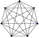
The notation for a complete graph is Kn, where n is the number of nodes in the graph. We can do little math here and see that the number of edges in Kn is n(n − 1)/2 edges (a triangular number). Here are a few more proprieties and terms, which I am not going to bother to define here, that apply to these things. I really recommend you take some time and look these up. It will give you a real feeling of just how complicated graph theory can become from just “edges and nodes” as your only tools.
- Kn is a regular graph of degree (n − 1). Each vertex has the same number of neighbors;
- All complete graphs are their own maximal cliques. A clique is a subset of nodes that are complete.
- Complete graphs are maximally connected as the only vertex cut which disconnects the graph is the complete set of vertices.
- The complement graph of a complete graph is an empty graph. The complement of a graph is a complete graph of the nodes minus the set of nodes that are actually in the graph.
Because all possible edges exist in the complete graph, all we need is a table with the nodes. We put the table in a view with a cross join on itself, remember to remove the edges on only one node (x, x) and you are done.
|
1 2 3 4 5 6 7 8 9 10 |
CREATE TABLE Nodes (node CHAR(1) NOT NULL PRIMARY KEY); CREATE VIEW Complete_Graph (node_1, node_2) AS SELECT N1.node, N2.node FROM Nodes AS N1 CROSS JOIN Nodes AS N2 WHERE N1.node <> N2.node; |
Disconnected Graphs
Going back to Mr. Gardner’s original posting, he seemed to be looking for a graph in which all of the subgraphs are complete (or cliques if you want to use that term). Here is a guess at the DDL he would need:
|
1 2 3 4 5 6 7 8 9 10 11 |
CREATE TABLE Directed_Graph (in_node CHAR(1) NOT NULL, out_node CHAR(1) NOT NULL, CHECK (in_node <> out_node), PRIMARY KEY (in_node, out_node)); INSERT INTO Directed_Graph VALUES ('A', 'B'), ('B', 'A'), ('B', 'C'), ('C', 'B'), –- ('A', 'C'), ('C', 'A'), ('D', 'E'), ('E', 'D'); |
The original data actually did not have a complete subgraph. It was missing the {(‘A’, ‘C’), (‘C’, ‘A’) }edges in the graph; I am going to make an assumption that this is what he wanted. This is why a general graph has to be represented as pairs of nodes in a table. However, if we can force something into a special subtype of graph, then we can do some representational tricks in the tables. Notice how many assumptions are built into this schema. An edge cannot come back to the node from which it started. The intent seems to be to provide an undirected graph by having to paths between every pair of nodes. The safer way to do this would be to use a view:
|
1 2 3 4 5 6 7 8 9 10 11 12 13 14 15 16 |
CREATE TABLE Base_Graph (in_node CHAR(1) NOT NULL, out_node CHAR(1) NOT NULL, CHECK (in_node < out_node), PRIMARY KEY (in_node, out_node)); INSERT INTO Base_Graph VALUES ('A', 'B'), ('B', 'C'), ('D', 'E'); CREATE VIEW Undirected_Graph (node_1, node_2) AS SELECT in_node, out_node FROM Base_Graph UNION ALL SELECT out_node in_node FROM Base_Graph; |
Further notice that we have no explicit path between all the nodes. For example, there is no explicit relationship between ‘C’ and ‘A’. however, you can find a path from ‘A’ to ‘B’ to ‘C’, which will put those three nodes into a subgraph. In this sample date, we have two disconnected subgraphs:
|
1 2 |
Group 1: {'A', 'B', 'C'} Group 2: {'D', 'E'} |
The initial proposed solutions to construct the subgraphs were essentially procedural traversal, dumping pairs of nodes into a temp table and incrementing a counter.
Let us try getting out of a procedural mindset and starting to think in sets instead. Let us give each subgraph a name, and a member node. Essentially, this directly models. The diagram I just gave you a paragraph or two ago. The next question is how do we get names for the subgraphs. I will propose the simple solution that each subgraph takes the name of the lowest element in it. This would give us a table that looks like this:
|
1 2 3 4 5 6 7 8 9 10 11 12 13 14 15 16 17 18 19 |
CREATE TABLE Subgraphs (subgraph_name CHAR(1) NOT NULL, member_node CHAR(1) NOT NULL, PRIMARY KEY (subgraph_name, member_node)); INSERT INTO Subgraphs VALUES ('A', 'A'), ('A', 'B'), ('A', 'C'), ('D', 'D'), ('D', 'E'); SELECT subgraph_name FROM Subgraphs AS S WHERE subgraph_name = @in_subgraph_name AND member_node IN (@in_node_1, @in_node_2) GROUP BY subgraph_name HAVING COUNT(member_node) = 2; |
Let us start with some basic questions we might ask about subgraphs. The obvious one is whether or not the two nodes belonged to the same subgraph. This was pretty easy to ascertain; ask if both of them are in the subgraph by name.
After that, we can compare two subgraphs with a simple set difference on the member nodes. A better trick is to merge two of these disjoint graphs by adding another edge. The algorithm should be fairly straightforward. Given (‘@x1’, ‘@x2’), find to which subgraph each of the new nodes belong. If the new nodes are already in the same subgraph you are done. But if they belong to two different subgraphs, then update the greater subgroup name to the lesser subgroup name.
Regular Graphs
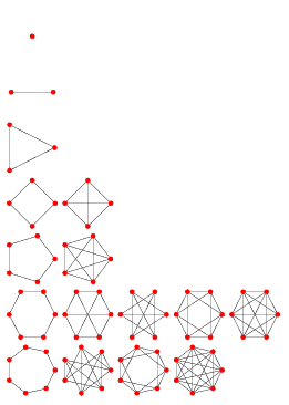
Regular graph has the same number of edges coming out of all of its nodes. There is a simple formula for telling you how many edges a regular graph with (n) nodes which each have (r) neighbors ; M = ½nr. Here is a quick set of illustrations for regular graphs for one to seven nodes, with a varying number of edges per node.
Number of Vertex (n) degrees for each Vertex (k)
|
2 |
1 |
||||||||
|
3 |
2 |
||||||||
|
4 |
1 |
2 |
3 |
||||||
|
5 |
2 |
4 |
|||||||
|
6 |
1 |
2 |
3 |
4 |
5 |
||||
|
6 |
2 |
4 |
6 |
||||||
|
8 |
1 |
2 |
3 |
4 |
5 |
6 |
7 |
||
|
9 |
2 |
4 |
6 |
8 |
|||||
|
10 |
1 |
2 |
3 |
4 |
5 |
6 |
7 |
8 |
9 |
Obviously a set of (k) nodes can have no more than (k -1) neighbors. This is probably easier to see with some pictures:
Let us try to build a table for the (5, 4) regular graph. Constraints will assure that all the neighbors are different, and will give us a key, the form of a row for each node and its neighbors. It is a little easier if we make sure all of the neighbors are in sorted order from left to right. Before anyone starts yelling at me. Yes, I would consider the neighbors to be repeated group.
|
1 2 3 4 5 6 7 8 9 10 |
CREATE TABLE Regular_5_4 (node CHAR(1) NOT NULL PRIMARY KEY, neighbor_1 CHAR(1) NOT NULL, neighbor_2 CHAR(1) NOT NULL, neighbor_3 CHAR(1) NOT NULL, neighbor_4 CHAR(1) NOT NULL, CHECK (node NOT IN (neighbor_1, neighbor_2, neighbor_3, neighbor_4), CHECK (neighbor_1 < neighbor_2), CHECK (neighbor_2 < neighbor_3), CHECK (neighbor_3 < neighbor_4)); |
It is easy to fill in this table by hand for a small graph, but gets a little harder as the graph gets bigger. Not too surprisingly there is a program for this purpose; http://www.mathe2.uni-bayreuth.de/markus/manual/genreg.html.
Graph Isomorphism
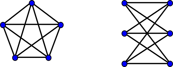
The graph isomorphism problem is simply to decide if two graphs are identical. This sounds easy but you have to find which node corresponds to which other node. For example, these two graphs look different but they are in fact the same (Credit: Wikipedia). This means that we have a mapping of all the nodes in one graph to a corresponding node in the other graph, and that all the edges can also be matched. Is a fairly easy idea, but it is probably better to show it with a picture:
|
Graph G |
Graph H |
An isomorphism |
|
|
|
f(a) = 1 |
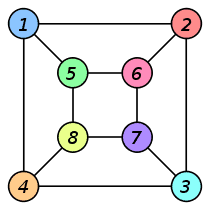
Like many things in graph theory, this problem is a lot harder than it first looks. This is why there was so much excitement in 2016 October when László Babai posted an abstract of a talk he was presenting on Tuesday, 2015 November 10 in Chicago for a new algorithm to solve the Graph Isomorphism (GI) problem (it also solves some related problems, but ignore that for now).
This created a lot of excitement when it was first announced because it was a significant advance. But it did not last long because we got an update on 2017 January 4, when its originator, László Babai, posted a retraction. There is nothing wrong with the bulk of the paper, but he found a flaw in the timing analysis that alters the result from quasipolynomial time to subexponential time. Harald Helfgott (University of Göttingen and CNRS) spotted the error.
Babai’s algorithm is general. However, if we have a particular type of graph, then we have got a tremendous advantage about knowing whether two of them are isomorphic. For example, there is an effect with only one complete graph for any set of in nodes, and only one regular graph for (n) nodes and (r) edges. You think about it. It is kind of dull, but it is important.
For this article. I am going to assume that you know the nested set model for trees. The tree is a graph that has a whole bunch of properties, such as not having any cycles, having (n-1) edges, where n = number of nodes, etc. In fact, trees are so special that Donald Knuth does a lecture every year on them at Christmas time. Yes, it is called the Christmas tree lectures. There is quite a lot of articles on the nested set model on the Internet. I even have a whole book on various ways representing trees (“Joe Celko’s Trees and Hierarchies in SQL for Smarties; 2nd Edition”; ISBN: 9780123877338).
However, one of the advantages of the nested set model for trees is that we have separated the nodes from the structure. Two trees T1 and T2, are isomorphic if the sets of (lft, rgt) pairs are identical. The simple EXCEPT set the difference operator will work. You have to do a little more work. If you are comparing a subgraph to another subgraph. It simply means subtracting constants from both the (lft, rgt) values to get them to a canonical form.
Isomorphism is in many ways weaker than equality. The two trees will have to have the same number of nodes obviously, but the nodes do not have to be the same. Furthermore, the subtrees have to have the same shape but do not have to have the same position in the tree structure. For example, the mirror image of a tree is isomorphic to it
|
1 2 3 4 5 6 7 8 9 10 11 12 13 14 |
CREATE TABLE Personnel (emp_name CHAR(10) NOT NULL PRIMARY KEY, lft INTEGER NOT NULL UNIQUE CHECK (lft > 0), rgt INTEGER NOT NULL UNIQUE CHECK (rgt > 1), CONSTRAINT order_okay CHECK (lft < rgt)); INSERT INTO Personnel VALUES (‘Albert’, 1, 12), (‘Bert’, 2, 3), (‘Chuck’, 4, 11), (‘Donna’, 5, 6), (‘Eddie’, 7, 8), (‘Fred’, 9, 10); |
Here is a second table, with different nodes and a different subtree ordering.
|
1 2 3 4 5 6 7 8 9 10 11 12 13 14 |
CREATE TABLE Personnel_2 (emp_name CHAR(10) NOT NULL PRIMARY KEY, lft INTEGER NOT NULL UNIQUE CHECK (lft > 0), rgt INTEGER NOT NULL UNIQUE CHECK (rgt > 1), CONSTRAINT order_okay CHECK (lft < rgt)); INSERT INTO Personnel_2 VALUES (‘Al’, 1, 12), (‘Bob’, 10, 11), (‘Chic’, 2, 9), (‘Didi’, 7, 8), (‘Ed’, 5, 6), (‘Frank’, 3, 4); |
If you want to take a pencil and write out the two trees, you can map the names. The gimmick is that this get harder as the tree gets bigger. The only thing you have got going for you is that if two trees are isomorphic, then they have the same number of nodes, and the same number of leaf nodes (it does not work the other way!); Both of these are obviously easy to compute with the nested set model (if you forgotten, a leaf node has the property that (rgt – lft) = 1).
I will offer one of my books as a prize for anyone who can come up with a procedure that can do such a mapping. My book on trees has procedures for moving subtrees underneath their root nodes, but trying to do this on a tree of any size is very, very expensive.
Functional Graphs
A functional graph has to be a directed graph. Think of each node in the graph as representing a function. You can have any number of incoming edges, but only one outgoing edge; it models how a function works (many inputs, one and only one output). Weisstein, Eric W. “Functional Graph.” From MathWorld – A Wolfram Web Resource. http://mathworld.wolfram.com/FunctionalGraph.html. This means that the number of nodes in a functional graph has to be equal to the number of out degree edges. Another interesting property of functional graphs is that it can have one and only one cycle.
Planar Graphs
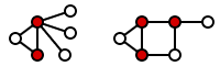
A planar graph is one that can be drawn on a plane without any edges having to leave the plane and cross over each other. In English, think of it as being that we can lay out our roads in such a way that we do not have any overpasses. They happen to be very important for designing circuit boards. It means a board can be printed without using jumpers (electrical overpasses) and increasing the cost of the board.
If you want to play with it, go to http://www.flashandmath.com/mathlets/discrete/graphtheory/planargraphs.html. You can grab the vertices in the sample. Graphs and move them around. It is kind of fun, but there has better ways to determine whether a graph is planar. In particular, if the graph contains one of these two sub graphs, then it is not planar. The Polish mathematician Kazimierz Kuratowski provided a characterization of planar graphs in terms of forbidden graphs, now known as Kuratowski’s theorem.
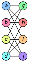
A finite graph is planar if and only if it does not contain a subgraph that is a subdivision of K5 (the complete graph on five vertices) or K3,3 (complete bipartite graph on six vertices, three of which connect to each of the other three). This is also known as the utility graph because of the famous puzzle. The puzzle is to connect three utilities (water, gas, electric) to three houses (A, B, C) without crossing over the supply lines of any other utility. It is impossible to do it on a plane, but fairly easy to do it if you put your houses and utilities on the surface of a torus (doughnut).
Vertex Covering
Social Network marketing depends on finding “The Cool Kids”, the trend setters that know everybody in a community. In some cases, it might be one person. The Pope is fairly well-known among Catholics, for example, and his opinions carry weight. Here are two vertex coverings taken from a Wikipedia article on this topic.
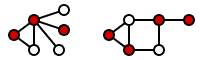
Neither one of them is minimal. You can actually do each of them with one less node in each set
Formally, a vertex cover of an undirected graph G is a set C of vertices such that each edge of G is incident to at least one vertex in C. The set C is said to cover the edges of G. Informally, you have a weird street map and want to put up security cameras at intersections (nodes) in such a way that no street (edge) is not under surveillance. We also talk about coloring the nodes to mark them as members of the set of desired vertices.
Graph Databases
Graphs are a good tool because they are so general, the computer science majors usually only get look at trees and perhaps a basic introduction. Only math majors seem to take a whole quarter of graph theory.
There are no ANSI or ISO Standard graph query languages. We have to depend on proprietary languages or open source projects. They depend on underlying graph databases, which are also proprietary or open source projects. Support for some of the open source projects are available from commercial providers; Neo4j is the most popular such products and it “went commercial” in 2009 after a decade in the open source world. This has happened in the relational world with PostgreSQL, MySQL and other products, so we should not be surprised.
Some of the graph databases were built on an existing data storage system to get started, but then were moved to custom storage engines. The reason is simple; performance.
There is no equivalent to SQL in the Graph Database world. Gremlin is an open source language that is based on traversals of a property graph with a syntax taken from OO and the C programming language family. (https://github.com/tinkerpop/gremlin/wiki). There is syntax for directed edges and more complex queries that look more mathematical than SQL-like.
Cypher is a declarative graph query language that is still growing and maturing, which will make SQL programmers comfortable. It is not a weird mix of odd ASCII charterers, but human readable keywords in the major clauses. Most of the keywords like WHERE and ORDER BY are inspired by SQL.
You need to look at http://www.graph-database.org/ for PowerPoint presentations on various graph language projects. AS of 2014, it seems to be off-line, but may come back. This field will be in flux for the next several years, but you will see several trends. The proposed languages are declarative, and are borrowing idea from SQL and the Relational Model. For example GQL (Graph Query Language), has syntax for SUBGRAPH as a graph version of a derived table. Much like SQL, the graph languages have to send data to external users, but they lack a standard way of handing off the information.
It is probably worth the effort to get an open source download of a declarative graph query language and get ready to update your resume.
Concluding Thoughts:
Graph databases require a change in the mindset from computational data to relationships. If you are going to work with one of these products, then you ought really to get math books on graph theory. Here is a short list of good introductory books:
- “A First Course in Graph Theory” by Gary Chartrand, Ping Zhang (ISBN: 978-0486483689)
- “Graph Theory” by Ronald Gould (ISBN: 978-0486498065)
- “Introduction to Graph Theory” by Richard J. Trudeau (ISBN: 978-0486678702)
- “Introductory Graph Theory” by Gary Chartrand (ISBN: 978-0486247755)


Load comments