
The series so far:
- Introduction to Game Development with Unity and C#
- Using C# Functions in Your Animations
- Procedural Generation with Unity and C#
- Pathfinding with Unity and C#
- Extending the Unity Editor with C#
- Using Unity UI and C# to Create a Tic-Tac-Toe Game
When creating enemy AI (Artificial Intelligence) it is often important to specify paths for your enemies. Enemy pathfinding can be useful for all types of games, be it stealth games or even fast paced action games. This pathfinding is often done by using a navigation mesh, or ‘navmesh,’ to find their way around. A navmesh is a type of data structure that is applied to objects to aid in pathfinding through complicated spaces. Video games began to see navigation meshes used more frequently as early as 2000.
As with many things, Unity has a simple way to create a pathfinding system for your objects. This easy process will allow you to get your basic AI off the ground quickly and allow you to create a more complex AI from there. In this example you’ll be creating a navigation mesh that an object will use to make its way to several points that you place in the environment. You will craft an area that you can ‘bake’ a navigation mesh in to start, create an object, and give the object a script that it will use to travel to different waypoints. From there you will set up these waypoints and assign them to the object in order to create a path for your object to follow endlessly.
Setting Up
First you will need to create a project. Open Unity and select New in the top right corner of the window as shown in Figure 1.

Figure 1: Creating a new project
Name this project Pathfinding and make sure it’s a 3D project (it should be by default). Specify a file path for your project. Your project creation window should look similar to Figure 2. Click Create project once the form is complete.
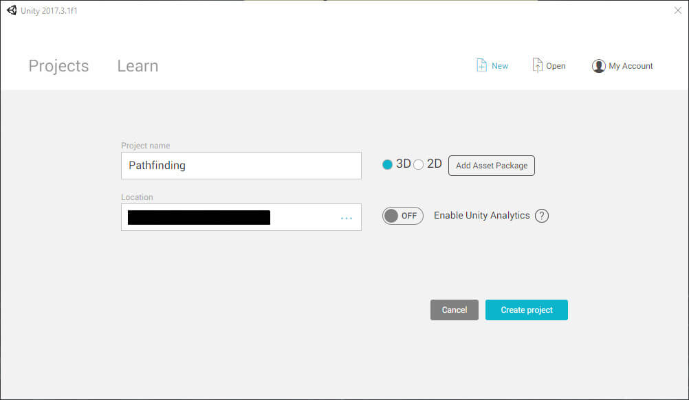
Figure 2: Naming the project
Allow Unity a moment to create the project. Once it’s finished, the first thing that you’ll need to do is create an area for the navmesh. Start by selecting the Create menu in the Hierarchy window then selecting 3D Object and then Cube. Figure 3 shows where to select the cube object for creation.
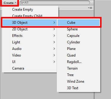
Figure 3: Creating a new cube object
This first cube object will be the floor of this scene. Name the object Floor and give it an X Scale of 20 and a Z Scale of 20. Figure 4 shows the final result of the Floor object in the Inspector window.
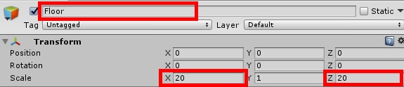
Figure 4: Renaming object to Floor and setting its scale values
Creating the Scene
Now you should make some obstacles for the object to navigate around. Your scene can be as simple or as complex as you like. Figure 5 shows an example scene that you can use.
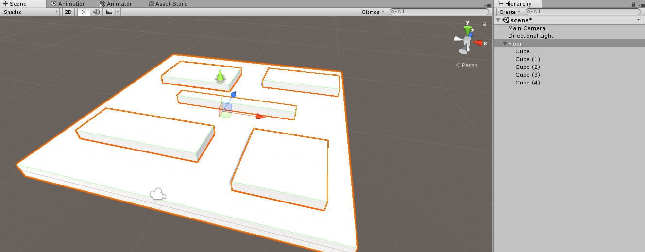
Figure 5: An example scene
If you want a better view of your scene when creating it, you can move the scene camera around by right-clicking in the Scene window and moving the mouse. Zoom in and out of the Scene window by scrolling your mouse wheel in the Scene window until you see everything you want view.
To create some obstacles, go to the Create menu once again and under 3D Object select Cube. Duplicate the cube as many times as you wish, then set a scale, rotation, and position for each cube using the Transform component in the Inspector window. Note: the cube objects will probably need to have a Y Position value of about 0.25, this way the cubes won’t be below the floor. Also, it is recommended that the cubes should have a Y Scale of at least 2. Your cube objects can be arranged in any way you like, but if you wish to replicate the scene in Figure 5 you may refer to Table 1 for the sizes and positions.
Table 1: The position and scale of all objects used in the example figures
|
Object |
Position X |
Position Y |
Position Z |
Scale X |
Scale Y |
Scale Z |
|
Cube |
1.13 |
0.25 |
0 |
10 |
2 |
1 |
|
Cube (1) |
6.04 |
0.25 |
5.87 |
7 |
2 |
3 |
|
Cube (2) |
-3.73 |
0.25 |
-5.32 |
9 |
2 |
3 |
|
Cube (3) |
-3.73 |
0.25 |
4.64 |
7 |
2 |
4 |
|
Cube (4) |
6.05 |
0.25 |
-5.87 |
5 |
2 |
5 |
Once you’ve set up your cubes, go ahead and parent them to the Floor object by selecting all your cube objects and dragging them onto the Floor object in the Hierarchy. Note: In the Inspector window it will look like the positions and scales change after parenting them to the Floor object. These values are their local position and local scale. You do not need to edit them.
If you wish, you may also create a material for the floor so that you can more easily tell the difference from the floor to the walls you have created. To create a material, right click in your Assets window and select Create->Material like in Figure 6.
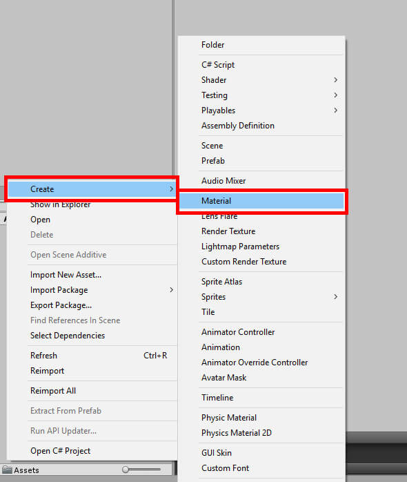
Figure 6: Creating a new material
After creating the material, give it the name Floor as seen in Figure 7.
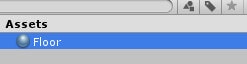
Figure 7: Renaming the material to Floor
Now you just need to set a color other than white for it. With the Floor material selected, head over to the Inspector window and double-click the color picker near the top like in Figure 8.
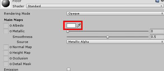
Figure 8: Opening the color picker
In this example, the color has been set to grey, but it can be whatever color you desire. Figure 9 shows the Unity color wheel and the RGB values used in this example.
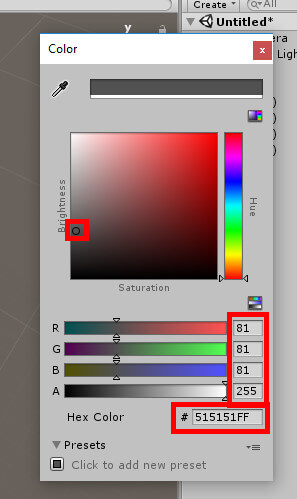
Figure 9: Example color for the Floor material
Finally, to set the Floor material to the Floor object, select the Floor object from the Hierarchy and under the Mesh Renderer component select the Materials option like in Figure 10.
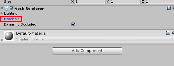
Figure 10: Opening the Materials menu
This will reveal some properties where you can change the material the object is using. Click and drag the Floor material from the Assets window into the Element 0 field in the Inspector like in Figure 11. Once complete, your floor will have a grey color to it, making it easier to tell apart the floor from the walls.
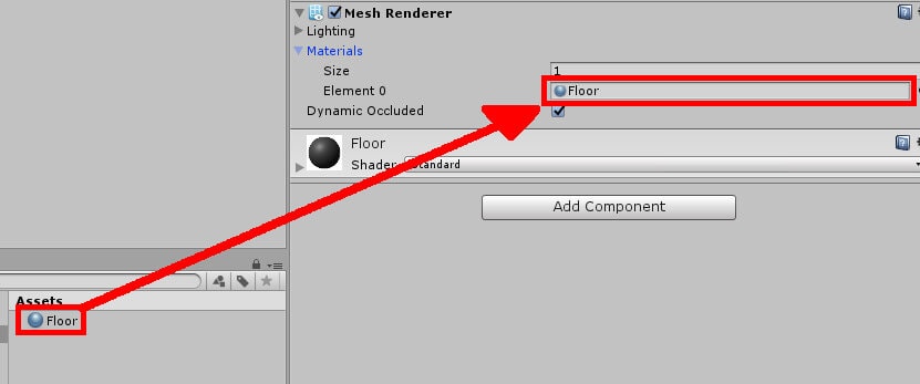
Figure 11: Applying the material to the Floor object
Now there needs to be an object that to navigate the area you have created. Once again, open the Create menu at the top of the Hierarchy and navigate to 3D Object->Cube to create another cube object. Be sure to set its position values to X 0, Y 1, Z 1.5 in the Inspector window. Note: you may need to adjust this depending on your scene layout. Give the cube the new name Object. When finished, your Hierarchy window should look similar to Figure 12.
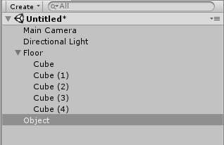
Figure 12: The current Hierarchy window
You can come back to this object in a moment, but before continuing you should go ahead and create the navmesh that will be used in your project. To do this you will need to navigate to Window->Navigation to open the Navigation window. Figure 13 shows where to find this.
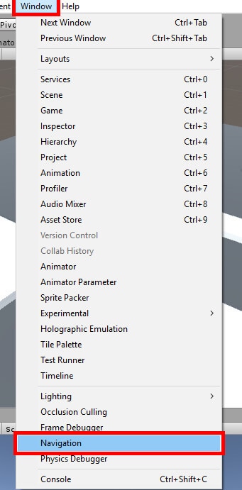
Figure 13: Opening the Navigation window
This should open the Navigation window where the Inspector window was earlier. By default, Object should be selected in the Navigation menu. Before continuing, make sure that the Floor object is selected in the Hierarchy window, else the process of creating the navmesh won’t work. Make sure All is selected under Scene Filter (once again, it should be by default) then check the Navigation Static checkbox. If you see a message asking if you want to enable the Navigation Static flag for the child objects, click Yes, change children. When finished the Navigation window should look like the one in Figure 14.
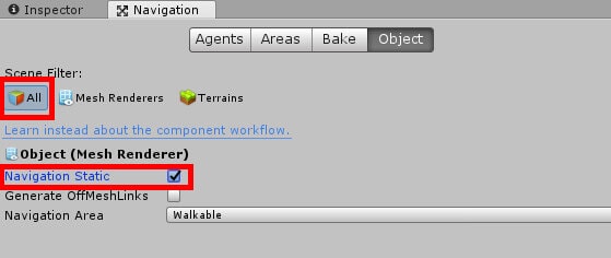
Figure 14: Setting properties for the navmesh
Next, select the Bake option in the Navigation window as seen in Figure 15.
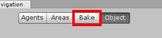
Figure 15: Opening the Bake menu
Once selected you will be greeted with the Bake menu. This is where the navigation mesh will be created. You can set properties like the radius and height here to change how the navmesh will turn out once it is finished ‘baking,’ which is the process of creating the navigation mesh from Unity’s end. For this project, you may leave all properties at their default values. Before creating the navmesh, you will need to save your scene. Once your scene is saved, go ahead and select the Bake option near the bottom of the Bake menu as seen in Figure 16 to create the navmesh.
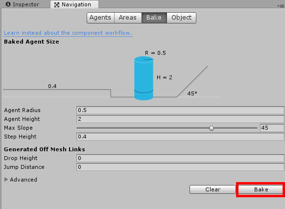
Figure 16: Baking the navmesh into the scene
You may need to allow a moment for Unity to create the navigation mesh before continuing. After Unity completes the navmesh creation process, your scene window should look similar to Figure 17.
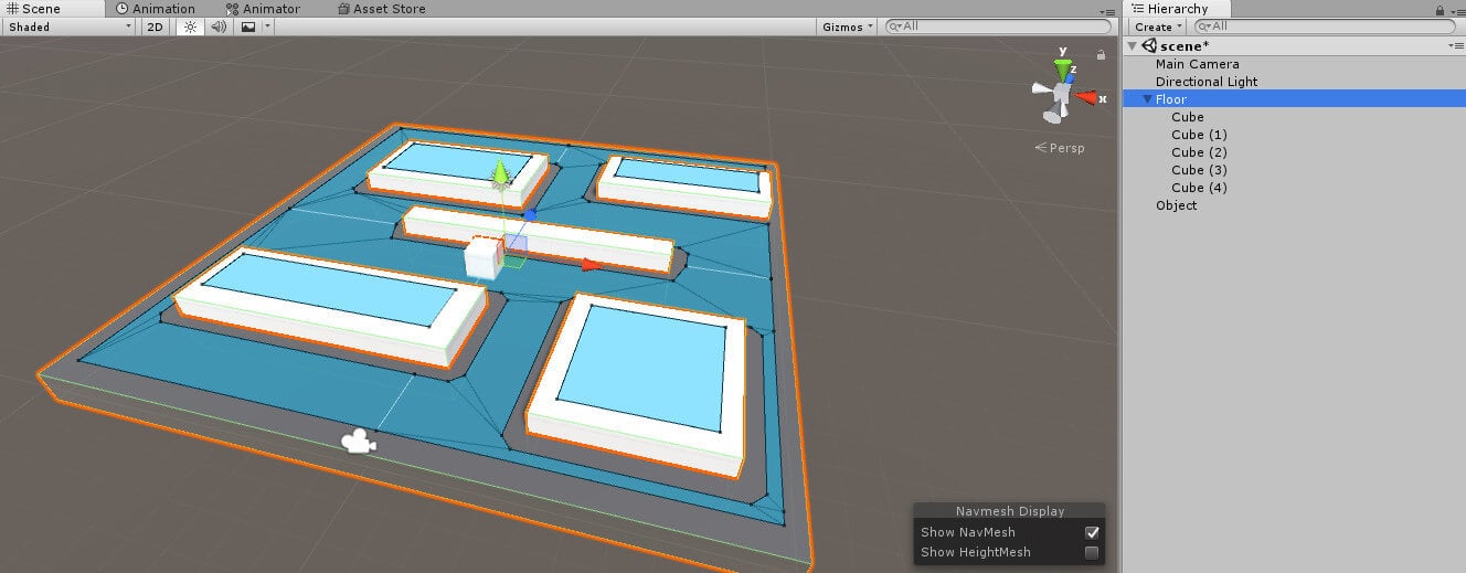
Figure 17: Example navmesh
Switch back to the Inspector window by clicking Inspector near the top of the Navigation window like in Figure 18.
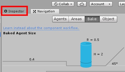
Figure 18: Switching to the Inspector window
Select Object in the Hierarchy to complete the setup. The last thing you need to do is give Object a new component called Nav Mesh Agent. To do this, click the Add Component button in the Inspector window. Figure 19 shows where this button is.
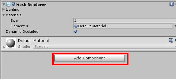
Figure 19: Adding a new component
Using the search bar, search for Nav Mesh Agent. Once found, click on the component like in Figure 20 to add it to the Object object.
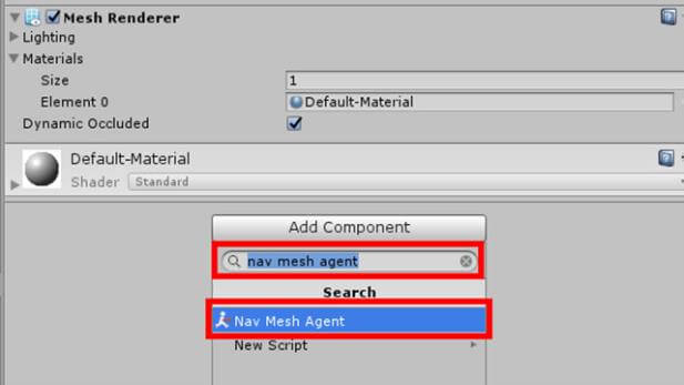
Figure 20: Adding the Nav Mesh Agent component
The Nav Mesh Agent component allows an object to navigate the scene using the navmesh you just created. There are several properties you can change such as how fast it goes, if it automatically brakes, or adjusting the obstacle avoidance radius. In this project you can leave all those alone if you wish, as the default settings will work perfectly with this project. Now the only step remaining before adding C# code is to create another new component for the object, this time a script component. Click the Add Component button again and this time search for ‘new script. Once found, select new script’ to create a new script. Give it the name Pathfinding and make sure the language is set to C Sharp. Select Create and Add to create the script and attach it to Object. Figure 21 shows how the setup should look.
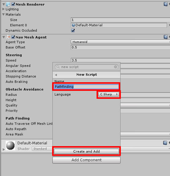
Figure 21: Creating the Pathfinding script
With the new script created, it is now time to open Visual Studio and create the Pathfinding script. Double click the Script field under the Pathfinding component like in Figure 22 to open Visual Studio and begin writing this object’s pathfinding code.
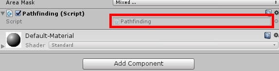
Figure 22: Opening the script in Visual Studio
Creating the Code
Before any code can be written a library will need to be added in Visual Studio. Just underneath the line using UnityEngine; enter the following line of code:
|
1 |
using UnityEngine.AI; |
This line will allow you to get the Nav Mesh Agent component that you attached earlier to Object. It will also give you the tools needed to have the object move between different points you’ll be setting up for it in a moment. Now, just underneath the line that says public class Pathfinding : MonoBehaviour enter the following code:
|
1 2 3 |
public Transform[] points; private NavMeshAgent nav; private int destPoint; |
First, you will be making a public array of Transforms simply called points. This array will store the locations of the different points that will be set up in the next section. The object this script is attached to will make its way to each point one by one until you end the game. It will navigate towards these points using the Nav Mesh Agent component, and the code will store a reference of that component in the nav variable. Finally, there’s the destPoint integer, which will be used to cycle through the different points laid out for Object. At this point, your code should look similar to the code seen in Figure 23.
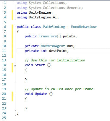
Figure 23: Getting the UnityEngine.AI library and declaring all needed variables
Now, in the Start function, you’ll need to enter a single line of code that will allow you to get a reference to the Nav Mesh Agent component at the very start of the game. Simply enter the following code into the Start function:
|
1 |
nav = GetComponent<NavMeshAgent>(); |
Next, go to the Update function. Before entering anything in this function, rename it to FixedUpdate. The difference between Update and FixedUpdate is that Update will run once every frame, whereas FixedUpdate is capable of running zero, one, or more times per frame. If, for example, your game is running at thirty frames per second, your FixedUpdate can make sure physics calculations are consistent and in synch with the global physics timestep of your game. Thus, it is recommended that any physics updates such as movement should be placed within the FixedUpdate. With that in mind, add the following code to the FixedUpdate function.
|
1 2 |
if (!nav.pathPending && nav.remainingDistance < 0.5f) GoToNextPoint(); |
Here you’re checking to see if the object has reached its destination or not. If it has not reached its destination (the next point in its list), then nothing happens. However, if it has reached its destination, it will call the GoToNextPoint method to find the next point to travel to. By now your Start and FixedUpdate functions should look like Figure 24.
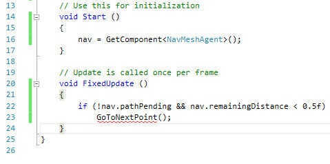
Figure 24: The Start and FixedUpdate functions
Finally, the GoToNextPoint method must be created. Underneath the FixedUpdate, function enter the following code:
|
1 2 3 4 5 6 7 8 9 |
void GoToNextPoint() { if (points.Length == 0) { return; } nav.destination = points[destPoint].position; destPoint = (destPoint + 1) % points.Length; } |
As stated above, the GoToNextPoint method will find the next point for the object to travel to. However, if the points array has nothing in it, it will instead cancel the method execution. This can help prevent any accidental errors from not entering anything into the array. After checking the length of the points array, it will then go on to set Object’s next destination and find the next point in the list to have ready for the next time this method is called.
Once this method has been written, this script will be complete. Figure 25 shows the completed code along with the code for the GoToNextPoint method. Save the script and return to the Unity editor.
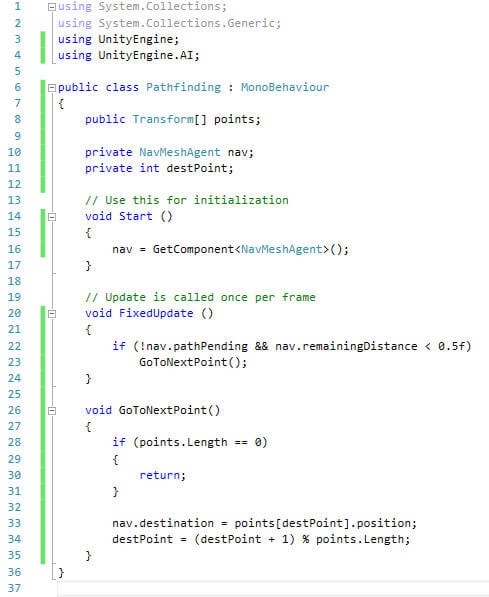
Figure 25: The completed Pathfinding script
Completing the Project
To finish the Pathfinding project, you simply need to create several points for the Object to travel to. Once again, click the Create button in the Hierarchy and select 3D Object->Cube to create a new cube object. Make sure its Y Position value is set to 1 (X and Z can be any value, so long as it’s within the map you created) in the Inspector. Also disable the Box Collider component by clicking the checkbox next to the name of the component. Set the X, Y, and Z scale to 0.25.
With your new Point object in place, create a new material to help identify the points. Name this material Point and give it whatever color you wish (the example will use green). Assign the Point material to the Point object like you did with the Floor object and material. Finally, set the X, Y, and Z scale of 0.25. The properties of the Point object should look similar to Figure 26.
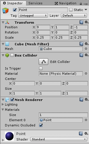
Figure 26: The Point object properties
Next, create duplicates of the Point object by selecting Point in the Hierarchy and pressing Ctrl+D. You can have as many Point objects as you wish, but this example will have a total of five Point objects. Once these objects are created, move each Point object to a different position on the map. Figure 27 shows an example of what the map with points will look like. Remember that yours may not look exactly like the image, depending on how you choose to set up your scene.
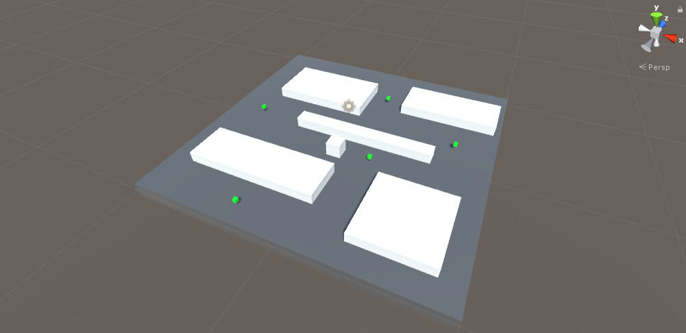
Figure 27: Points with new material and size
Now you’ll just need to set the Point objects as the values of the Points array created in your Pathfinding script. Select Object and lock the Inspector window onto Object so that you don’t accidentally change screens when selecting other objects. Figure 28 shows where to click to lock the window.
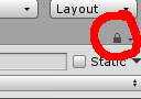
Figure 28: Locking the Inspector window
Select all the Point objects in the Hierarchy and drag them into the Points field in the Pathfinding component like in Figure 29.
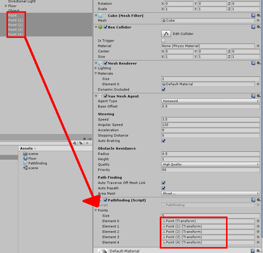
Figure 29: Setting the values of the Points array
Finally, you should reorient the camera, so you can see what Object is doing when you press the play button. Be sure to unlock the Inspector window, then choose the Main Camera object from the Hierarchy and set the following values:
- Position X: 0
- Position Y: 20
- Position Z: 0
- Rotation X: 90
When finished, the Transform component for your Main Camera object should look like the one seen in Figure 30.
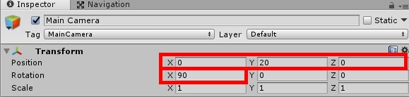
Figure 30: Setting up the Main Camera rotation and position
Once you have finished setting up the Main Camera object, press the play button at the top of the Unity editor and watch Object move to the different points you set up for it. When you’re done watching, click the play button at the top again or press Ctrl+P to exit play mode. Rearrange the points to create a new path for your object and play the game again. Notice how it both consistently finds the fastest route and is smart enough to avoid the walls you created, regardless of your point layout. Figure 31 shows this project in action.
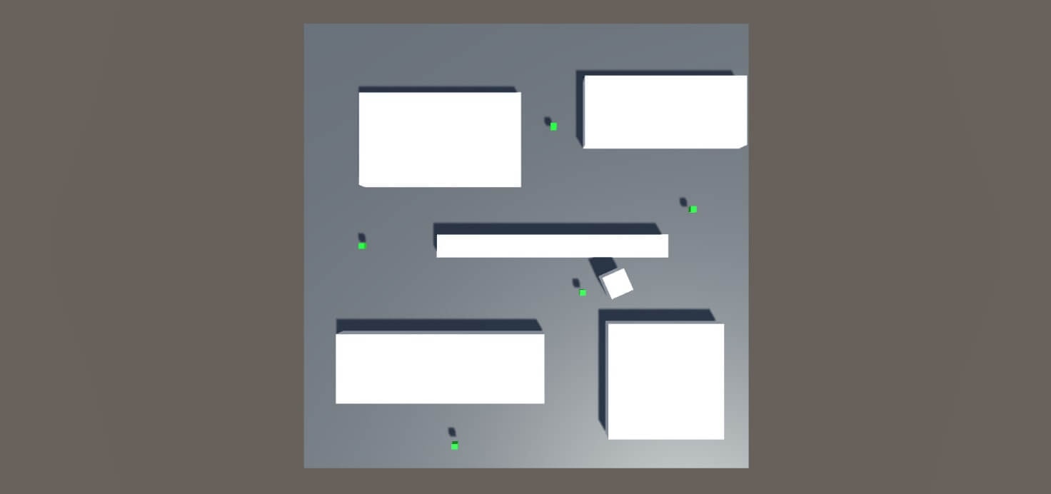
Figure 31: The Pathfinding project in action.
Conclusion
With the project completed you have learned how to create a navigation mesh in your scene and have an object look at that navmesh to figure out where it can and cannot go. Unity makes it easy to quickly create this navmesh as well as put together a simple pathfinding system for an object. You can apply this knowledge in virtually any type of game, be it a stealth game where you assign enemy patrol routes for the player to avoid or in a puzzle game where you can decide where certain parts of a puzzle move to. The Unity engine handles a lot of the heavy lifting for you, permitting you to put more time into making a fun game without getting bogged down in trying to create simple AI.
Load comments