
In the first of this series of articles about Hyper-V Networking and Configuration, we learned the basics of Hyper-V networking.
The networking configuration or scenarios explained in this 2nd part can be used on Hyper-V running on Windows Server 2008, Windows Server 2008 R2 and Windows Server 2012. Even though there are new changes introduced in the Hyper-V networking on Windows Server 2012, but those changes do not provide significant improvements on “How to” methods when configuring Hyper-V networking configuration scenarios explained in this part of this series. The article focuses more on “how to” achieve a specific requirement/configuration that you have received from your customer, the best way to do it. We also learn why we should just not create Network Virtual Switch to achieve the simple configuration/requirement.
We will also learn networking tagged and untagged traffic, and best practices for Hyper-V Networking.
I recommend reading the first part of this series if you have not already. There are a few terms which I have explained in the first part of this series.
Some Terms:
- VMMS.EXE
- VMMS.EXE is the main process at the heart of Hyper-V Server. It controls all other aspects such as Virtual Machines (child partitions), Hyper-V Networking, the creation of Hyper-V Virtual Network types and communication between Virtual Machines via Virtual Network Switches.
- VLAN Tagged
- The VLAN Tagged is a method used by the protocols to tag a packet.
- MAC Table
- A Table on the Network Switches which has the addresses of all the devices connected to it.
- VSP/VSC
- VSP is called Virtual Service Provider and VSC is called Virtual Service Client. VSP/VSC design is implemented when Integration Services Component is installed in Virtual Machine.
Hyper-V Networking Best Practices
Avoid creating unnecessary virtual Network Switches on the Hyper-V Host
For VMMS.EXE, the process of ensuring proper communication between Virtual Machines via Virtual Network Switches is an extra overhead. The more switches you have, the worse it gets. Hyper-V allows you to create unlimited Virtual Network Switches but that does not mean that it is a good idea to create a virtual switch for each requirement, because VMMS.EXE must maintain the configuration and communication between Virtual Machines connected to them.
Assign the first two Physical Network Cards for Virtual Machine traffic.
You should separate Hyper-V management traffic from Virtual Machine traffic. A typical Hyper-V Host should have at least the following Physical Network Cards attached to it.
- NIC 1 – Assigned to parent partition for management to the Hyper-V Host.
- NIC 2 – Assigned to parent partition for Storage communication from Hyper-V or Virtual Machine.
- NIC 3 – Assigned to the Virtual Machines for communications with LAN, Virtual Machines on the same Hyper-V Server, or Virtual Machines on the Remote Hyper-V Server.
- NIC 4 onwards – Additional Network Adaptors based on your requirement.
Always select a configuration method for Hyper-V Networking in a particular order of preference.
When you come across any networking requirement that needs to be configured on Hyper-V Server, use the order of preference that I’ve listed below to achieve the configuration you need. The best way is to use the “Hyper-v Virtual Network Switch and VLAN Tagging” method. Other methods can also be used depending on your requirements, but consider them in this order.
- Hyper-V Virtual Switch and VLAN Tagging Method
- Hyper-V Virtual Switch Method
- Firewall Method
- Different subnet Method
- Another Physical NIC Method (applies when External networking is configured)
Always Team Hyper-V Host Physical NICs
Microsoft does not provide support for teaming Physical Network Adaptors on a Hyper-V Server running on earlier operating Systems except Windows Server 2012. Windows Server 2012 provides built-in NIC Teaming feature to provide load-balancing and fault-tolerance mechanisms for Hyper-V Server and Virtual Machines both.
Note: Virtual Machines must be running Windows Server 2012 Operating System before you can configure NIC Teaming.
Always install Integration Services on Virtual Machines
Microsoft provides an Integration Services Component for Hyper-V Virtual Machines which is equivalent to VMWare tools in VMWare, and VM Additions in Virtual Server. You should install Integration Services on supported Guest Operating Systems to achieve the high-speed communications between child and parent partitions. The Integration Services component implements the VMBus communication channel which has direct access to the Virtual Service Providers running on the Parent Partition.
Hyper-V Networking Configuration Scenarios
In referring to these scenarios, I’ll assume that you’ve read Part 1 of this article series here, so please do so if you have not done so already.
Virtual Network Switch implementation in Hyper-V provides the following functionality:
- Virtual Network Switch operates at Layer 2.
- The Switch maintains a table called MAC Table. This MAC Table contains the MAC Addresses of Virtual Machines connected to it.
- Hyper-V Virtual Network Switch has a learning algorithm in which it learns the MAC address of a Virtual Machine connected to it. This MAC Address, once learned, is stored in the MAC Table of the Virtual Network Switch.
- VLAN IDs can be specified on each Virtual Network Switch except Private Virtual Network Switch.
- You can assign only “one” VLAN ID on property of Virtual Network Switch.
- One VLAN ID can be specified on NIC of Virtual Machine. You can have 12 Virtual NICs created for a Virtual Machine.
- Unlimited Virtual Machines can be connected to a Virtual Network Switch.
- A Hyper-V Virtual Network Switch can be configured in Access Mode and not in Trunk Mode. Please refer to Part 1 of this article series to understand the Access and Trunk Modes.
- There are a few requirements before you can use the VLAN ID or VLAN in Hyper-V:
- A physical network adapter that supports VLAN configuration.
- A physical network adapter that accepts packets with VLAN IDs Tagged.
System Administrators/consultants can get confused when it comes to configuring the Hyper-V Networking for any project or customer requirements. For most of the requirements, administrators either do not have idea as to how this is achieved in Hyper-V or end up configuring a complex networking configuration that hits problems which results in poor performance on the Hyper-V Server and in the communications between Virtual Machines.
This topic covers a few scenarios for Hyper-V Networking and explains how you can use them to accomplish your requirement without impacting performance and communications between Virtual Machines. We will explain a couple of scenarios and describe the configuration methods we use to achieve them.
Most of the project requirements end up either with “Allow” or “Do Not Allow” or both. We will learn how you use configuration methods mentioned below to meet “Allow” or “Do Not Allow” specifications.
Each scenario that I’ll be describing here can be configured using one of the methods that I’ve already listed in the ‘best practices’ section.
Let me give you a simple example. As you know by reading Part 1 of this article series, a Private Virtual Switch in Hyper-V allows you to have communication between Virtual Machines connected to the switch and communication with same Hyper-V Server, but it does not allow communication between Virtual Machines on the Remote Hyper-V Server. The overall objective of the Private Virtual Switch is to block communications for other Virtual Machines or Servers on the LAN.
If this is what you need to accomplish as part of your requirement then you can create the switch. However, is it necessary to create a Private Virtual Switch or could you accomplish the configuration with other configuration methods?
You will have noticed in the ‘Hyper-V Networking Best Practices’ section that you should not create a Virtual Network Switch for the sake of it, because it increases the overhead for the VMMS.EXE process. This is where I hope that these scenarios come handy because you can adapt the other methods explained in this topic to achieve the results to need.
We will start by looking at a simple scenario first, and then finish the topic with a rather more complex one. Before we start working on the configuration part to accomplish the Hyper-V Networking requirement, here is a checklist:
- Is connectivity to External networking required?
- Is it really necessary to create a Virtual Network Switch or can I use existing one?
- If yes which one I should use? External, Private, or Internal?
- Can the requirement be achieved using the VLAN Tagging system?
- Can I just use a firewall in Virtual Machine or Hyper-V Host to accomplish it?
- Can I configure different subnets if it is only to meet “Allow” or “Do Not Allow” specs of the requirement?
Scenario 1:
You have two departments in your organization; Finance and HR. You have created two Virtual Machines for each department. These Virtual Machines are hosted on the same Hyper-V Server. You need to make sure HR Virtual Machines talk to each other or have communication between them but no other Virtual Machines, whether they are running on the same Hyper-V server (basically Finance Virtual Machines), Virtual Machines running on remote Hyper-V server or servers located on the Physical LAN.
This is very simple scenario. The requirement clearly indicates that the connectivity to the External Network or Physical LAN is not required for both types of Virtual Machines. That means we should avoid creating an unnecessary External Virtual Network Switch
Let’s apply one of the methods that we discussed earlier in order to get the results we want.
Using a Hyper-V Virtual Switch Method
Once configured using a Hyper-V Virtual Network Switch, the solution looks like as shown in Figure 1.1.
In Figure 1.1 you can see that HR Virtual Machines (VM1and VM2) are connected to HR Virtual Network Switch and Finance Virtual Machines (VM3 and VM4) are connected to Finance Virtual Switch.
The switch “HR Virtual Switch” in Figure 1.1 is a “Private Network Switch” type. This is to ensure that the communication is only allowed between HR virtual machines. Please note there is no VLAN ID configured on the Virtual Network Switch at this point of time.
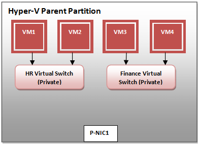
Figure 1.1 – Scenario 1 Configuration: Using a Hyper-V Virtual Switch
So, to achieve the first scenario using a “Hyper-v Virtual Switch” method, we have created two private Network Virtual Switches. Many administrators or consultants end up implementing this configuration into production, which results in extra overhead for Hyper-V VMMS.exe process.
What if you need to reduce the communication overhead by avoiding creating unnecessary Virtual Network Switches? Can we achieve the requirement by just creating one Virtual Network Switch and using VLAN Tag method? Yes, we can.
Using Hyper-V Virtual Switch and VLAN Tagging Method
Figure 1.2 shows the configuration of the same requirement using a VLAN Tagging system. A common Virtual Network Switch has been created. Since the Private Virtual Network Switch does not support VLAN Tagging, we have created an Internal Network Virtual Switch named “Common Virtual Switch”.
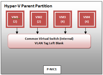
Figure 1.2 – Scenario 1 Configuration: Using a Hyper-V Virtual Switch and VLAN Tagging Method
The “Common Virtual Switch” is not configured with the VLAN Tag ID. The VLAN ID is left blank on the Virtual Network Switch but is configured on the respective Virtual Machines.
As you can see, both VM1 and VM2, which belong to HR department, have been configured with VLAN ID 2. VM3 and VM4, which belong to Finance department, have been configured with VLAN ID 4.
When configuring VLAN Tag ID, you need to ensure that you configure the VLAN Tag ID on all the connected devices (VM1, VM2, VM3, VM4 and Common Virtual Switch in this example).
The requirements have been achieved both by using a Hyper-V Virtual Network Switch and Hyper-V Virtual Network Switch with VLAN Tagging. Both these methods achieve the same results in that they do not allow HR’s Virtual Machines to talk to any other Virtual Machines and Servers connected to the LAN. The latter method avoids the creation of unnecessary Virtual Network Switches.
Since the problem is all about blocking the communication between a set of Virtual Machines, you can always achieve the same results by using a Firewall or different subnets for HR Virtual Machines.
Any network packet sent from any Virtual Machine (VM1 through VM4) will be tagged with its VLAN ID and then forwarded to the Common Virtual Network Switch. The Common Virtual Network Switch follows an algorithm to see if the packet needs to be discarded or forwarded. We will explain this in more detail in the later part of this article series.
Scenario 2:
There are three departments; Accounting, Sales and Finance. You have created three Virtual Machines; VM1 for Accounting, VM2 for Sales and VM3 for Finance. There are three Physical Servers; Server1, Server2 and Server3 located on the LAN. These are running with SQL Server. Accounting Virtual Machine (VM1) needs to access Server1 to store its data, Sales Virtual Machines (VM2) needs to access Server2 to store its sales data, and Finance Virtual Machine (VM3) requires access to Server3 to store its Finance-related data. Management has decided that the Virtual Machines should not be able to talk to each other. They should be able to communicate with the Physical Servers as mentioned below:
- VM1 Access to Server1 only.
- VM2 Access to Server2 only.
- VM3 Access to Server3 only.
The big difference that we see between Scenario 1 and Scenario 2 is the communication to the External LAN (e.g. VM1 through VM3 talking to Server1 through Server3 on LAN). The moment you see the requirement for External communication you’ll think of using an External Virtual Switch.
To achieve the requirements of this second scenario, you can use any of the configuration methods as discussed earlier but the most suitable methods to use are:
- Using another Physical NIC Method (applies when External networking is configured).
- Using Hyper-V Virtual Switch and VLAN Tagging Method.
Using another Physical NIC Method (applies when External networking is configured)
This method is common and most administrators who are not familiar with Hyper-V Networking end up using it. In this configuration method, we need to have:
- Three Physical NICs for each Virtual Machine (VM1, VM2 and VM3).
- Three External Virtual Network Switches.
The following disadvantages are associated with this method:
- Traffic is segregated for each Virtual Machine to its own Physical NIC only.
- Virtual Machines do not use the complete speed/GB of a Physical Network.
- No other Virtual Machine is allowed to use the Physical Network of other Virtual Machines.
- More External Virtual Network Switches need to be created.
- Configuration and communication overhead for VMMS.exe process.
- Cost associated with the physical devices (Network Adaptors).
Let’s take a look at the other method available.
Using Hyper-V Virtual Switch and VLAN Tagging Method
This is a better method for such a configuration. Only one External Virtual Network Switch is created and mapped to NIC1 of the Hyper-V Host. Once configured using Hyper-V Virtual Network Manager, the layout looks like Figure 1.3 below:
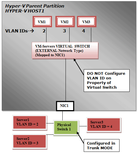
Figure 1.3 – Scenario 2 Configuration: Using a Hyper-V Virtual Switch and VLAN Tagging Method
As you see in Figure 1.3, the following configuration has been applied to each device/Virtual Machine:
- Each Virtual Machine (VM) is configured with a unique VLAN ID.
- The Servers on the LAN are configured with the matching VLAN ID.
- The Physical Switch (green) is configured in Trunk Mode to allow traffic for VLAN ID 2, 3 and 4.
- VM-Servers Virtual Switch, which is a External Virtual Network Switch is configured with “no” VLAN IDs!
The most interesting part of this configuration is the External Virtual Switch. This Hyper-V Virtual Network Switch is not configured with any VLAN IDs. If you assign any VLAN ID on the Virtual Switch, the traffic will be tagged with that VLAN ID and the communication will be allowed only for that VLAN ID Tagged packet. The VM-Servers Virtual Switch in Figure 1.3 is authoritative for all the traffic from Virtual Machines connected to it (i.e. it is able to receive all traffic and forward them without modifying the VLAN ID in the packet it receives). This process is explained in the next topic.
Hyper-V Networking Tagged and Untagged Traffic
When a network packet is sent from a Virtual Machine to another Virtual Machine on the same Hyper-V Server, a Virtual Machine on Remote Hyper-V Servers, or Servers connected to LAN, then the packet is first received by the Virtual Network Switch with the following Information:
- Source Address
- Destination Address
- VLAN Tag ID
We’ll explain the logic behind the Tagged and Untagged VLAN traffic for two virtual machines communication (VM1 and VM2)
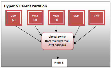
Figure 1.4 – VLAN and Virtual Switch Not Assigned any VLAN Tag ID
The Figure 1.4 shows a typical configuration of a Virtual Network Switch created on the Hyper-V Server with five Virtual Machines connected to it. The Virtual Network Switch is either an Internal Type or External Type. It is important to understand the communication between Virtual Machines, Virtual Network Switch and Physical NIC.
As you can see, Virtual Network Switch has not been assigned with any VLAN ID. It is left blank. This is what happens when VM1 sends a packet to the network of Virtual Switch:
- VM1 sends out a packet with VLAN ID Tagged 2.
- The packet is received or discarded by the Virtual Network Switch based on the following logic:
- Is Virtual Network Switch configured in Access Mode? E.g. Is VLAN ID assigned to the Virtual Network Switch?
- If yes, does it match with the one it has received from VM1?
- If yes receive the packet and forward it based on the Virtual Switch Type configured.
- To all the ports (all Virtual Machines basically) of switch.
- To P-NIC1 if it is an external Virtual Switch.
- If no, discard the packet as Virtual Network Switch is not configured to accept the packets with VLAN ID other than what has been assigned to it.
- If yes receive the packet and forward it based on the Virtual Switch Type configured.
- If yes, does it match with the one it has received from VM1?
- Is Virtual Network Switch configured in Access Mode? E.g. Is VLAN ID assigned to the Virtual Network Switch?
- Once the packet is forwarded by the Virtual Network Switch, it is the destination Virtual Machine which must decide whether it needs to retain the packet or discard it based on the logic mentioned below:
- Does VLAN ID tagged in packet match with the one configured on the Virtual Machine?
- If yes, receive the packet.
- If no, discard the packet.
- Does VLAN ID tagged in packet match with the one configured on the Virtual Machine?
In short, it depends on the destination device whether to receive the packet or discard it based on the configuration.
The Hyper-V Virtual Network Switch does not, as one might assume, work the same way as a Physical Switch. A Physical Switch can be configured in both modes (Access and Trunk) but a Hyper-V Virtual Network Switch can be configured only in “Access Mode” as of today.
Conclusion
In this article we saw how Hyper-V Networking can be configured to meet a wide range of requirements, and I have described the configuration methods that are available for you to use. We also learned the Hyper-V VLAN Tagged and Untagged traffic and how it affects the communication between Virtual Machines and Network Virtual Switches. We also learned the best practices we need to follow when configuring Hyper-V networking in production.
In the next in this series of articles, we will primarily focus on the following topics:
- Configuring Hyper-V Networking using SCVMM.
- Three Ways to configure VLAN Trunking for Hyper-V Virtual Machines.
- Hyper-V Networking VMBus and VSP/VSC design and how it improves the communication.
- A Complex Hyper-V Networking Configuration requires use of all Virtual Network Switch Types and VLAN configuration.
This document contains proprietary information and is protected by copyright law.
Copyright © 2026 Red Gate Software Limited. All rights reserved
Load comments