
Have you ever looked at a game and wondered how it achieved its appearance? Perhaps it looked like it was ripped straight from a comic book or the world was drawn perfectly to convey an eerie atmosphere. There are three components that create the look of the game, them being textures, materials, and shaders. Textures are simple images, which is what the material can use to define a surface. Shaders are small scripts that hold the mathematical calculations of every pixel rendered in game and are largely based on the lighting input and configuration of materials. Shaders can play a pivotal role in creating unique and interesting visuals for a project.
To create a shader, one must be prepared to do a little graphics programming. Here, the aim will be to get your feet wet with a Unity shader of your own creation. The code in this shader will specify what to do with the very vertices that make up the triangles which in turn make up the geometry the material is applied to. By the end you should be able to create a material from this shader that draws an object in a wireframe. You can also change its color, the wire thickness and its transparency to get exactly the look you want in the object.
Creating the Shader
As of this writing, Unity has unveiled a new program called Unity Hub, which is where project creation will occur. Start by selecting the New button in the top right.
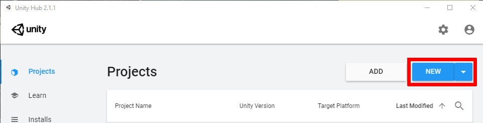 Figure 1: Creating a new project in Unity Hub.
Project creation proceeds as usual from here. Give it a name, select the type of project, and designate a location for the project. Once you have finished, click the create project button to begin.
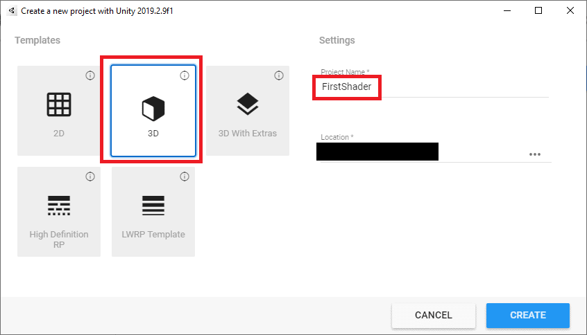
Figure 2: Project creation
Of course, in order to test out any shader you create, you’ll first need an object or two. Here two objects will be made, a cube and a sphere, using the Create menu in the Hierarchy.
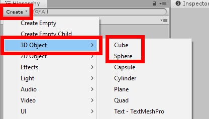
Figure 3: Creating objects
To better view the objects, increase their scale to five, then place them anywhere you’d like. The example below places the Cube object at -3, 1.5, 2 position and rotates its x axis by 45 and its y axis by 25. Your Sphere object can be placed at 5, 1.5, 0 position with no rotation.
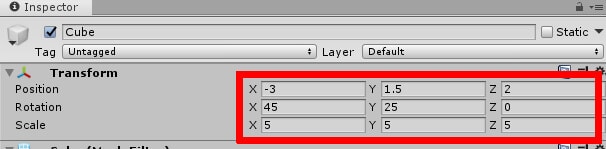
Figure 4: Cube object’s placement, rotation, and scale.
The environment is now set, which means it’s time to begin creating the shader. Create your new shader by right clicking in the Assets window and selecting Create->Shader->Standard Surface Shader.
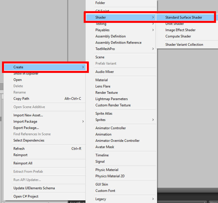 Figure 5: Creating a new shader.
You may name the shader whatever you wish, but the remainder of this writing will refer to this shader as MyShader. Now that this has been created, double click the newly created shader file to open Visual Studio and begin the coding process.
The Code
To recap, the shader in question will draw objects in a wireframe. For the uninitiated, a wireframe is a 3D model that is drawn with only the vertices and lines. There will be no textures or lighting on these wireframe objects. That removes some problems you would ordinarily have to figure out, but it presents some new ones as well. Drawing a series of triangles in code can yield its own set of challenges. Not only that, but the wireframe shader will have a slight glow to it as well as some user defined thickness and transparency.
Back to Visual Studio, you can see that the code here is not like what you usually program in Unity. There are some parts that use Unity’s Shaderlab, a language for writing shaders, while others incorporate more traditional C for Graphics (Cg) and C# code with a heavy leaning towards Cg. There are some familiar elements such as structs and void functions while on other lines you’ll see syntax like SubShader and LOD. Those will be explained as they come, but this writing will largely be focused on the Cg and C# elements. Now that the environment has been established, it’s time to get to work on the wireframe shader.
For starters, you can go ahead and delete all code currently within the shader. The shader you’re about to make will be created from scratch to more easily understand how all its parts come together. Once that’s done, enter the following:
|
1 2 3 |
Shader "Simple Talk/Wireframe Tutorial" { } |
All this first line does is set the menu location for the shader. When editing any material there is a Shader menu you can navigate to select which shader this material will use. In this case, MyShader is found at SimpleTalk->Wireframe Tutorial. This will be demonstrated after you finish coding the shader. Speaking of which, it’s time to begin the shader creation proper, starting with property declarations. This will go within the Shader pair of curly braces.
|
1 2 3 4 5 6 |
Properties { _Color("Color", Color) = (1, 1, 1, 1) _Wireframe("Wireframe thickness", Range(0.0, 0.005)) = 0.0025 _Transparency("Transparency", Range(0.0, 1)) = 0.5 } |
The general structure of a property is the variable name, the property’s designation in the editor, what kind of property it is, and then a default value. For example, the first variable is given the name _Color while in the editor it will display as whatever is in the quotations. Then you specify that it will be of the Color value type and give it a default color of white. _Wireframe and _Transparency are a little different in that their value types are given as a range of floats. This means in the Unity editor those variables can be edited by moving a slider.
Next comes the SubShader, which defines rendering passes and optionally can set up any state common to all passes. In other words, it’s the part that makes the shader what it is. The SubShader goes inside the Shader under the Properties section.
|
1 2 3 4 |
SubShader{ Tags { "Queue" = "Transparent" "RenderType" = "Transparent" } LOD 200 } |
At this point, the script should look like the below figure:
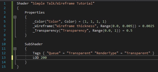
Figure 6: The shader so far.
Since you want the material born from this shader to be transparent, you give it both the render type of transparent as well as the queue in its tags. If you wanted a shader that still had a full object with wires around it, you would remove the queue tag to do so. As the ability to change the material’s transparency will be available, you need to let Unity know that the object is able to fade. You might wonder why you wouldn’t just set the color to have an alpha of zero to achieve the same effect. The reason is simple – it doesn’t affect anything. Materials appear to ignore the alpha value in the color selection on primarily focus on the RGB values. At that point, the biggest reason to keep the alpha value is tradition.
Tags can also be queried later in other C# scripts for whatever purpose you may need. This is similar to the typical tagging system seen when creating an object in Unity. Finally, there’s the LOD line with a number beside it. LOD stands for Level Of Detail and controls, you guessed it, the level of detail in the material. For example, if an object has a material that makes it look like a concrete tile, the LOD controls how nice looking that concrete tile can be. You would typically have multiple LOD options for various computer builds but since this is a wireframe shader it’s reasonable to assume that the material derived from this shader could run on a toaster.
Within SubShader you now must create a Pass. All the prep work is out of the way, meaning Pass will contain the code that defines the material’s appearance.
|
1 2 3 4 5 |
Pass { Blend SrcAlpha OneMinusSrcAlpha Cull Back } |
And here’s how the script looks now:
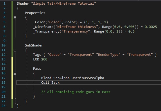
Figure 7: The shader with Pass included.
The Blend line exists to create transparent objects and nothing more. Cull Back is you telling Unity to not render polygons facing away from the viewer. There is also Cull Front, which does the opposite of Back and stops the rendering of polygons facing the viewer, and Cull Off which draws all polygons regardless if they are currently being viewed. This example chose Cull Back with the belief that it looks better but you may adjust this as you wish.
It’s now time to put those properties to use in some functions and structs. Before beginning, you’ll need to let Unity know that Cg is in use until otherwise noted by adding the following in Pass:
|
1 |
CGPROGRAM |
Then, under that create the following:
|
1 2 3 4 |
#pragma vertex vertexFunction #pragma fragment fragmentFunction #pragma geometry geometryFunction #include "UnityCG.cginc" |
The rest of the code all goes inside the Pass section. The pragma statements are very much like method declarations that you may normally find in a C# script. They will be defined later on in the coding process. At the end there’s an include statement, which lets the editor know you’ll be using some commonly used helper functions from that library. Now to create a couple structs:
|
1 2 3 4 5 6 7 8 9 |
struct v2g { float4 pos : SV_POSITION; }; struct g2f { float4 pos : SV_POSITION; float3 bary : TEXCOORD0; }; |
v2g stands for vector 2 geometry and contains a single variable – a float4 named pos, with SV_POSITION being what’s known as a semantic. Semantics is how you explain to the editor what the variable’s “intent” is. In this case, the intent is to output the clip space position of a vertex, this way the GPU knows where on screen to place pixels. The next struct, g2f (standing for geometry 2 fragment) has all the same info as v2g but with an additional float3 named bary which uses the TEXCOORD0 semantic. TEXCOORD0 is simply the first UV coordinate in the shader, given as a float3 in this example but can also be done with float2 or float4.
|
1 2 3 4 5 6 |
v2g vertexFunction(appdata_base v) { v2g o; o.pos = UnityObjectToClipPos(v.vertex); return o; } |
Earlier you wrote some pragma statements, which acted effectively as function declarations. It’s time to give those functions a little code to execute. First up is vertexFunction which, as the name suggests, gets the various vertexes ready for the next two functions. Then comes geometryFunction:
|
1 2 3 4 5 6 7 8 9 10 11 12 13 14 15 |
[maxvertexcount(3)] void geometryFunction(triangle v2g IN[3], inout TriangleStream<g2f> triStream) { g2f o; o.pos = IN[0].pos; o.bary = float3(1, 0, 0); triStream.Append(o); o.pos = IN[1].pos; o.bary = float3(0, 0, 1); triStream.Append(o); o.pos = IN[2].pos; o.bary = float3(0, 1, 0); triStream.Append(o); } |
Here the different triangles that make up an object are being drawn. This is possibly the busiest function in the whole script, though you’ll notice a pattern – a few lines of code are being repeated, just with different elements in the IN array and the bary value from the g2f struct being given different float3 values each time. There’s also an attribute at the top of the function specifying that the maximum vertex count per shape is three, which makes sense as it is triangles being drawn and thus only need three vertexes per triangle. The last step remaining is to change the object based on the color, thickness and transparency values the user enters.
|
1 2 3 4 5 6 7 8 9 10 11 12 |
float _Wireframe; fixed4 _Color; float _Transparency; fixed4 fragmentFunction(g2f i) : SV_Target { float value = min(i.bary.x, (min(i.bary.y, i.bary.z))); value = exp2(-1 / _Wireframe * value * value); fixed4 col = _Color; col.a = _Transparency; return col * value; } ENDCG |
You’ll notice the three variables kicking things off look awfully familiar. They share the name of the properties declared early in the script. Why the repeat? Remember that you’re currently working in the CGPROGRAM section and it needs to take in the properties defined early on to make any use of them. You can see their use implemented in fragmentFunction, where the object is given its assigned color, wireframe thickness, and transparency. Finally, the script ends with ENDCG, which tells Unity that Cg is not being used any longer.
All the code needed to give objects a wireframe appearance is complete. Save your work and go back to the Unity editor. If there are errors, they will appear in the Inspector window upon selecting the shader file in the Assets window.
Putting the Shader to Use
First, you’ll need to create a material that uses this shader. The easiest way to do this is to right click the shader file in the Assets window and navigate to Create->Material.
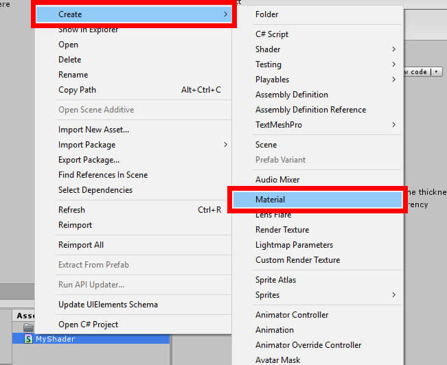
Figure 8: Creating a new material with MyShader
Name the material whatever you wish, then navigate to the Inspector window. If you look at the top of the Inspector window you can see the path Simple Talk/Wireframe Tutorial in the Shader menu. Selecting that drop down menu brings up the following:
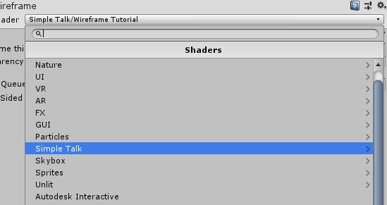
Figure 9: The Shader menu. You can see Simple Talk as an option.
In this menu you can select from any number of shaders, for this material, including the one just created. If you navigate to Simple Talk->WireFrame Tutorial you will select MyShader as the shader to base this material off of. Since you right clicked the shader and created the material from the context menu, this is not needed. However, you could still use this menu if you accidentally chose the wrong shader.
In a preview window at the bottom of the Inspector window you can see how the material will look on an object. Go ahead and assign a color to it. You can also specify how thick you want the lines to be and how transparent the object is.
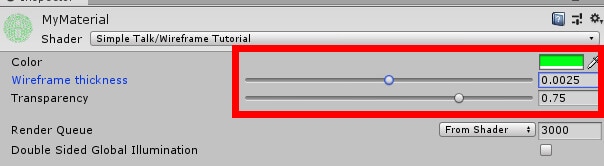
Figure 10: Changing material properties.
Your cube and sphere will need the material applied to them in order to better see the material, and by extension the shader, in action. Select an object and find its Mesh Renderer component in the Inspector. Under Materials there is a space to click and drag your new material in.
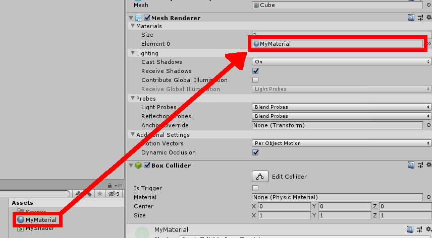 Figure 11: Setting object material.
Once you’ve done that, the project is finished, and you should see your objects take on its wireframe appearance. You can try playing with the values in the material to get different appearances.
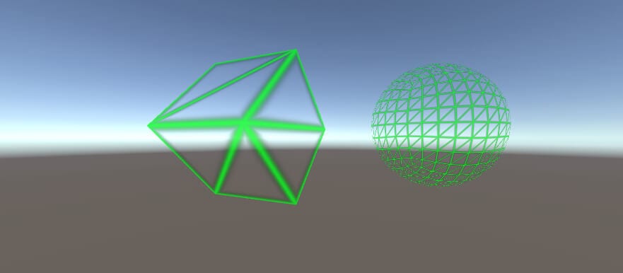 Figure 12: Cube and Sphere with new material.
Conclusion
As shaders go this is perhaps one of the more basic ones you can create. Still, pat yourself on the back for dipping your toe into graphics programming. One way you can expand on this knowledge is to study and recreate the default shaders in Unity. All you need to do is create a new shader file, open the code in Visual Studio and have a look around. Or, you can get experimental and try coming up with your own unique shaders.
This document contains proprietary information and is protected by copyright law.
Copyright © 2026 Red Gate Software Limited. All rights reserved
Load comments