
The Database Availability Group (DAG) is quite possibly one of the most important new features of Exchange 2010. With Exchange 2007, Microsoft introduced the concept of continuous replication, whereby the transaction logs were shipped between copies of the mailbox databases. While this has remained in Exchange 2010, there have been significant improvements in the overall high availability model.
By now, I’m sure that most Exchange professionals have read up on the features of the DAG from the official Exchange product documentation, and the numerous articles that exist on the Internet. However, if you haven’t, you can find out what all the fuss is about within the Exchange 2010 product documentation. Rather than discuss theory and possibilities, this two-part article will be of a more practical nature, and will cover the steps required to actually create and configure a DAG, discussing the features only where appropriate.
Most of what we will cover now will be related to the configurations that are necessary to make a DAG possible; the actual creation process itself is fairly simple. I’ll cover how to start using the DAG effectively in part 2. We’ll be working with a demonstration lab environment, which is quite basic as it’s only intended to demonstrate the concepts involved. As such, I strongly recommend that you don’t try and simply replicate this configuration in your production environment.
Lab Environment
First of all, it’s important to understand the lab setup that is to be used for this article, and which is illustrated in Figure 1. You can be see that the lab environment is a simple two-node DAG, consisting of two Exchange 2010 servers which are each running the Mailbox, Hub Transport and Client Access Server roles. These servers are called EX01 and EX02 respectively, and are running the Windows Server 2008 R2 Enterprise operating system. A third server exists, called DC01, which functions as the lab domain controller and DNS server. A single Active Directory domain exists, and all the servers are members of the same Active Directory site. Each mailbox server is also equipped with two network interfaces, although this isn’t a strict requirement to create a DAG (don’t worry if that seems a little enigmatic, as I will be expanding on this statement later in this article).
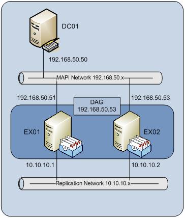
Figure 1: Lab Environment
The two-node DAG can be considered to be modeling a high availability solution within a single data center. However, this DAG configuration clearly cannot survive the loss of the data center itself, as no copies of the mailbox databases exist outside of the single site. A site-resilient DAG solution will be covered in future articles here on Simple-Talk.
Before we continue, we need to discuss an important design consideration regarding the load balancing of the Client Access Server role. In the configuration presented above, the Client Access Server role is coexisting on the same servers as the Mailbox server role. Since the mailbox servers are part of a DAG, which itself uses Windows Failover Clustering, it is not possible to implement Windows Network Load Balancing (WNLB) as the high availability mechanism for the Client Access Server role. As explained in the Exchange 2010 product documentation, under the section titled “Two-member DAG in Single Datacenter/Active Directory Site“, this is because WNLB and Windows Failover Clustering cannot be installed on the same server. Therefore, in this particular configuration, an external load balancing solution will be required, although that particular facet of configuration is outside the scope of this article.
DAG Components
There are various components that comprise a DAG, such as:
- A name:
Each DAG that is created in an Exchange 2010 organization requires a unique name, which ultimately becomes the name of the failover cluster. The name used for a DAG must be limited to a maximum of 15 characters. - A witness server:
If a DAG has an even number of mailbox servers contained within it, as is the case in our Lab Environment DAG, a witness server will be used to act as an additional vote in the cluster to maintain cluster quorum. A Hub Transport server is typically chosen as the witness server, as long as that server role is not running on a member of the DAG. In our lab environment, the only server outside of the DAG is the domain controller, and therefore this has been specified as the witness server. Bear in mind that such a configuration isn’t recommended for production environments, as will be discussed later. Finally, note that when creating a DAG, it is possible to leave out the witness server parameter, which will result in a Hub Transport server being automatically selected, provided that it’s located in the same Active Directory site and not also running the Mailbox server role. - A witness directory:
If a witness server name has been specified, a witness directory must also be specified; this is simply a folder or directory where a minimal amount of cluster information is stored. Although it is possible to choose any folder, consider choosing a folder that’s tucked out of the way, and therefore unlikely to be accidentally deleted because it is, for example, located on the root of the C: drive. - One or more IP addresses:
A DAG must have one or more IP addresses assigned to it. In our lab environment, the DAG is located in a single Active Directory site, and therefore just requires a single IP address. If the DAG is to span multiple Active Directory sites, then it naturally requires an additional IP address from each of the other Active Directory sites.
Network Configuration
First, a little background: The network configuration used within the DAG is crucial, as there are a number of specific configuration elements required for successful DAG creation and operation. It can be seen from Figure 1 that each DAG member has two network ports assigned to it. One network port functions as the MAPI network, which is used by other Exchange 2010 servers to communicate with the members of the DAG, whilst the other network port functions as a replication network, which is used for transaction log shipping and database reseeding.
In previous versions of Exchange which used clustering techniques for high availability, the networks were often referred to as the public and private networks. However, with Exchange 2010 it could prove advantageous to rename the network connections to MAPI and Replication respectively. Doing so could help with identification and troubleshooting, such as in situations where you need to monitor the network activity of individual networks.
In a previous article, I discussed the Exchange 2007 network port configuration for a Cluster Continuous Replication (CCR) environment, as well as how it was possible to have more than one network dedicated to transaction log shipping and database reseeding. You’ll be glad to know that the concept of using multiple network ports for transaction log shipping and database reseeding purposes hasn’t changed in Exchange 2010. However it should also be noted that the actual transaction log shipping method now uses a single Transmission Control Protocol (TCP) port, rather than the Server Message Block (SMB) method found in Exchange 2007.
However, in this article there is just one replication network available, meaning that, for high availability, transaction log shipping will ordinarily occur across this network. Should this particular network fail, Exchange 2010 will then ship transaction logs across the MAPI network. If multiple replication networks are deployed, Exchange 2010 will use these in a redundancy fashion until none are available, and then fall back to using the MAPI network.
In fact, Microsoft has made specific recommendations on how the MAPI and replication networks should be configured, and these are shown below, in Table 1:
|
Feature |
MAPI Network Setting |
Replication Network Setting |
|
Client for Microsoft Networks |
Enabled |
Disabled |
|
QoS Packet Scheduler |
Optionally Enabled |
Optionally Enabled |
|
File and Printer Sharing for Microsoft Networks |
Enabled |
Disabled |
|
IPv6 |
Optionally Enabled |
Optionally Enabled |
|
IPv4 |
Enabled |
Enabled |
|
Link-Layer Topology Discovery Mapper I/O Driver |
Enabled |
Enabled |
|
Link-Layer Topology Discovery Responder |
Enabled |
Enabled |
Table 1: Network Configuration
It is important to ensure that the networking configuration is correct on each Mailbox server before attempting to create a DAG. In the lab environment, the recommendations made in Table 1 have been followed and it was decided to enable the optional settings of the QoS Packet Scheduler and IPv6, as shown below in Figures 2 and 3. Be aware that if IPv6 has been disabled by de-selecting the check box in the networking interface properties, it should also be disabled within the server’s registry, as per the instructions that can be found in Microsoft Knowledgebase article 929852. It’s important to ensure that IPv6 is fully disabled, and not just disabled within the networking interface properties.
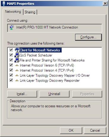
Figure 2: MAPI Network Configuration
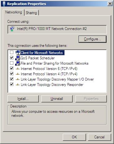
Figure 3: Replication Network Configuration
There are also a few more important changes that need to be made with regards to the networking configuration, before you can create your DAG. These are:
- Ensure that the default gateway is assigned only on the MAPI network interface and not, therefore, on the replication network interface.
- Ensure that there are no DNS server addresses configured on the replication network interface; these should only be configured on the MAPI network interface.
- It is also important to ensure that the Register this connection’s addresses in DNS option is not selected on the replication network interface. To clear this option on the replication network interface, perform these steps:
- With the replication network properties screen open, as shown in Figure 3, select the Internet Protocol Version 4 (TCP/IPv4) option and then click the Properties button
- In the resulting window, called Internet Protocol Version 4 (TCP/IPv4) Properties, click the Advanced button
- In the Advanced TCP/IP Settings window, click the DNS tab
- In the final resulting window, clear the Register this connection’s addresses in DNS check box, as shown in Figure 4
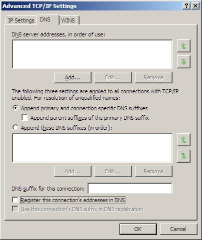
Figure 4: Disabling DNS Registration
- Set the network binding order so that the MAPI network is at the top of the list. To do this, follow these steps:
- With the Network Connections window open, press the Alt key to bring up the menu option.
- With the menu displayed, click Advanced and then Advanced Settings…
- In the resulting Advanced Settings window, ensure that the MAPI network is at the top of the connection order, as shown in Figure 5.
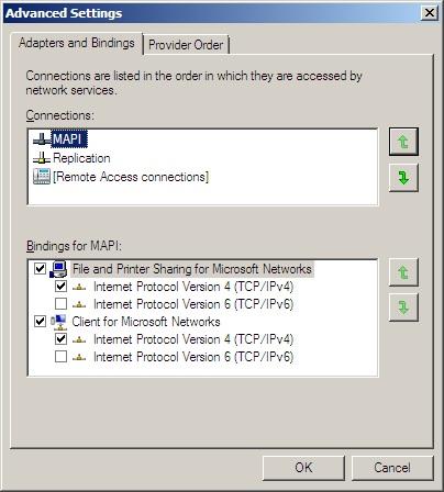
Figure 5: Network Connection Order
Creating The DAG
The DAG itself can be created either via the Exchange Management Console or via the Exchange Management Shell; in this article, I’ll be using the Exchange Management Shell.
Before the DAG is finally created, we need to discuss the requirements for the server which is hosting the file share witness. As discussed earlier in this article, the server hosting the file share witness must be outside of the DAG, and in our lab environment, only the domain controller is outside the DAG. Since this server isn’t running Exchange 2010, an additional configuration step must be performed to ensure that the Exchange servers have the permissions necessary to create the file share witness directory structure.
Specifically, you need to add the Exchange Trusted Subsystem universal security group to the local Administrators group on the domain controller. The Exchange Trusted Subsystem group can be found in the Microsoft Exchange Security Groups OU, as shown in Figure 6.
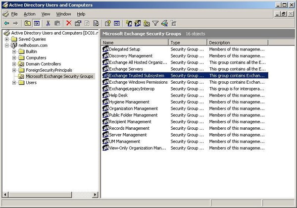
Figure 6: The Exchange Trusted Subsystem Group
Important:
Please note that this may be acceptable within a lab environment, but this isn’t a configuration that should be placed into a production environment due to the security implications of adding the Exchange Trusted Subsystem group to the local Administrators group on a domain controller.
With the group membership change made, it’s now time to create the DAG using the Exchange Management Shell. The cmdlet used to create the DAG is the New-DatabaseAvailabilityGroup cmdlet, which has a number of parameters associated with it. The full cmdlet for this lab is shown below, followed by an explanation of the parameters used:
|
1 |
New-DatabaseAvailabilityGroup -Name HeadOffice -WitnessServer DC01 -WitnessDirectory "C:\Program Files\Microsoft\Exchange Server\V14\HeadOfficeWitness" -DatabaseAvailabilityGroupIPAddresses 192.168.50.53 |
The parameters used are:
- Name:
This is simply the name of the DAG, which will become the name of the failover cluster, as mentioned earlier. In this example, the DAG name is HeadOffice. - WitnessServer:
This is the name of the server that will house the file share witness. - WitnessDirectory:
The WitnessDirectory parameter is the name of the folder or directory that will house the file share witness information. - DatabaseAvailabilityGroupIPAddresses:
This parameter is a comma separated list of IP addresses assigned to the DAG. In this example, the DAG has just a single IP address: 192.168.50.53. If the DAG was to contain mailbox servers in different Active Directory sites then it would require an additional IP address, and the list would read: 192.168.50.53,172.16.1.10
The results of running this cmdlet are shown in Figure 7; note the warning that the witness server is not an Exchange server or a member of the Exchange Servers security group:
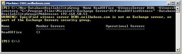
Figure 7: The New-DatabaseAvailabilityGroup Cmdlet
Running this cmdlet simply creates the DAG object in Active Directory; you can see from Figure 7 that the Member Servers field is currently blank, as there are no Exchange 2010 Mailbox servers currently configured as part of this new DAG. The DAG object concept was covered in a previous article, but I’ll briefly describe what you’ve just created again to make sure we’re all on the same page.
Using ADSIEdit, it is possible to view the configuration contents of the newly created DAG by first connecting to the configuration naming context, and then drilling down to find the DAG object as shown in Figure 8. This object has a class of msExchMDBAvailabilityGroup.
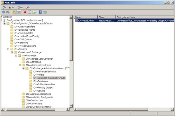
Figure 8: The DAG Viewed With ADSIEdit
By right-clicking the DAG object and bringing up its properties, a window similar to the one shown in Figure 9 will be seen, where it is possible to confirm that the correct parameters, as stated in the cmdlet, have been used to create the DAG. For example, it can be clearly seen from Figure 9 that the correct DAG name and witness server information has been used.
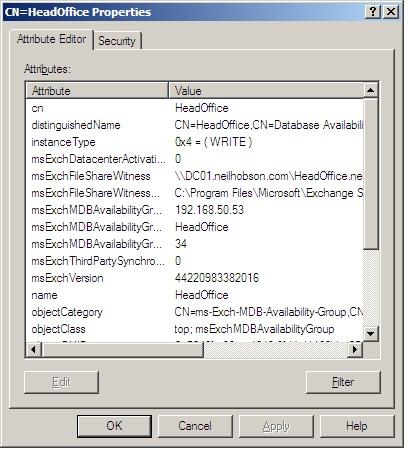
Figure 9: DAG Properties
Summary
So far, we’ve covered the configuration and creation of a two-node Exchange 2010 Database Availability Group, together with a brief explanation of DAG components and functionality. However, this is clearly just a tiny step towards achieving a truly High Availability Exchange Server environment, and simply having a DAG in place is not sufficient. Lastly, I cannot stress enough that the configuration I have demonstrated here is only appropriate in a controlled, non-production environment, and is purely intended to demonstrate the core concepts of creating the DAG.
The second part of this series will cover topics such as DAG logs, adding mailbox servers to the DAG, other DAG configuration options and managing database copies. These are not more ‘advanced’ topics as such, but merely the facts you will have to be familiar with it you want to make use of this superb and robust technology.
This article was commissioned by Red Gate Software, engineers of ingeniously simple tools for optimizing your Exchange email environment.
Learn more about Exchange Server Archiver and PST Importer.
Load comments