
This is the second and final article of a two-part series explaining the process of creating and configuring a simple two-node Database Availability Group (DAG) in Exchange 2010. In part one of this article, we covered topics such as the lab environment used throughout this discussion, the components that comprise a DAG, the overall network configuration requirements, and the process to actually create the DAG object using the Exchange Management Shell. If you haven’t read part one of this article, I strongly recommend that you do so before reading part two.
In this second article we will initially be examining the log files that are generated during the DAG creation and configuration processes, as these become invaluable when you are troubleshooting. Although we won’t really see deep examples of how to use these log files, this is still information you’ll be glad we covered. We will then move on to the more practical matters of adding the two mailbox servers (EX01 and EX02) to the DAG using the Exchange Management Shell, and also cover important DAG configuration parameters that can be adjusted after the DAG itself has been created. Towards the end of the article, once we have our DAG configured to our taste, I’ll talk a bit more about the Failover Cluster, show you how to add mailbox database copies to the two mailbox servers, and how to perform a process known as a database switchover.
As you can see, there is a lot of information to cover in this article, so let’s get started by examining the log files which are generated during the DAG creation process.
DagTask Logs
On the Exchange 2010 server where the New-DatabaseAvailabilityGroup cmdlet was executed, navigate to the C:\ExchangeSetupLogs\DagTasks folder, which will contain log files relevant to DAG creation and configuration tasks. Each log file name will be in the following format:
|
1 |
dagtask_{date and time}_{cmdlet} |
In this format, {date and time} refers to the date and time that the DAG cmdlet was executed, while {cmdlet} refers to the name of the DAG cmdlet that was executed. For example, the log file name shown in Figure 1 below is dagtask_2010-02-02_20-02-18.305_newdatabaseavailabilitygroup. After the first DAG cmdlet, such as New-DatabaseAvailabilityGroup, has been executed, there will naturally only be a single dagtask log file in the C:\ExchangeSetupLogs\DagTasks folder. As further DAG tasks are run, such as those involving the Set-DatabaseAvailabilityGroup cmdlet, additional dagtask log files will be created in the same folder.
With this in mind, it’s worth nothing that the setup log file that is created at the same time as the DAG itself (i.e. as a result of running the New-DatabaseAvailabilityGroup cmdlet for the first time) is worth investigating, and Figure 1 shows an example of this dagtask log file’s contents. In this particular log file, important configuration information is shown, such as the WitnessServer and WitnessDirectory cmdlet parameters, together with a clear indication that the DAG creation process was successful. Examining the contents of this log file will prove useful when troubleshooting DAG creation failures.
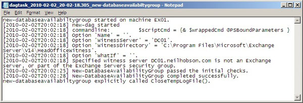
Figure 1: Contents of a Dagtask Log File
Adding Mailbox Servers to the DAG
Now, once the DAG has been created, the next step is to add the first mailbox server, EX01, to the DAG. To accomplish this, the Add-DatabaseAvailabilityGroupServer cmdlet will be used, which requires two parameters. They are the -Identity parameter, which identifies which DAG is being configured, and the -MailboxServer parameter, which identifies which mailbox server is being added to the DAG. Therefore, the full cmdlet to use is:
|
1 |
Add-DatabaseAvailabilityGroupServer -Identity HeadOffice -MailboxServer EX01 |
The Add-DatabaseAvailabilityGroupServer cmdlet performs the following tasks:
- First, a check is performed to see if the server EX01 is already a member of a DAG, as a mailbox server can only be a member of a single DAG.
- Next, the Windows Failover Cluster components are installed on that mailbox server (if they are not already present); this second task is being performed in Figure 2. Of course, if it is known when an operating system is being deployed that it will be for a mailbox server which will also be part of a DAG, then it is still perfectly acceptable to pre-install the Windows Failover Cluster components prior to running the Add-DatabaseAvailabilityGroupServer cmdlet.
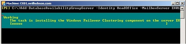
Figure 2: Installation of the Windows Failover Clustering Components
- Once the Windows Failover Cluster components have been installed, the Add-DatabaseAvailabilityGroupServer cmdlet creates the Windows Failover Cluster itself, which takes its name from the name given to the DAG. Therefore, in the lab environment, the failover cluster name is HeadOffice, as this is the name given to the DAG.
- Finally, the mailbox server EX01 is added to the DAG.
After the running of the Add-DatabaseAvailabilityGroupServer cmdlet, an additional dagtask log file will have been created in the DagTasks log folder mentioned earlier. This new log file contains plenty of useful information, such as the progress of the cluster formation, and the progress of adding the mailbox server to the DAG, as can be seen in Figure 3. Examining the contents of this log file will prove to be a useful exercise if you have any issues when adding a mailbox server to the DAG.
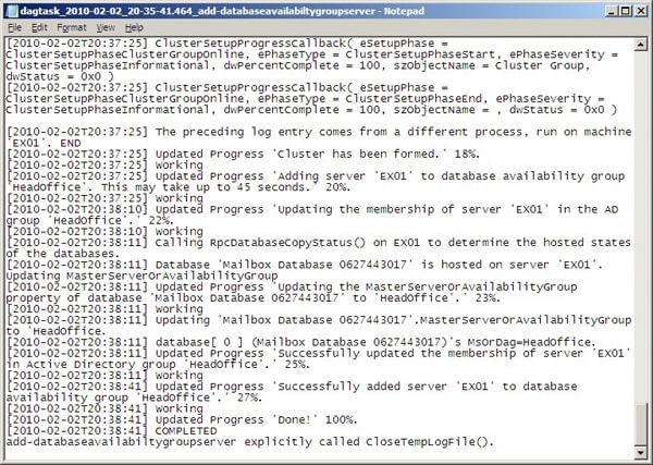
Figure 3: Dagtask Log File for Add-DatabaseAvailabilityGroupServer
Now that the first mailbox server has been added to the DAG, the Add-DatabaseAvailabilityGroupServer cmdlet needs to be repeated, specifying the second mailbox server EX02 as the server to add to the DAG. Thus, the cmdlet to achieve this is:
|
1 |
Add-DatabaseAvailabilityGroupServer -Identity HeadOffice -MailboxServer EX02 |
Once this cmdlet has completed, the properties of the DAG can be examined to confirm that both mailbox servers are now members of the DAG. To do this, the Get-DatabaseAvailabilityGroup cmdlet can be used, with the results of this cmdlet piped into the format-list (or ‘fl’ for short) cmdlet. To reduce the amount of information provided, we can filter the output to only show the ‘servers’ parameter, and so the command to achieve all of this is:
|
1 |
Get-DatabaseAvailabilityGroup HeadOffice | fl servers |
The result of running this cmdlet is shown in Figure 4, where it can be seen that both EX01 and EX02 are confirmed as members of this DAG:
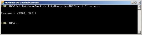
Figure 4: Confirming DAG Membership
Additional DAG Parameters
Now that you’ve got your Mailbox databases added to the DAG, the Set-DatabaseAvailabilityGroup cmdlet can be used to configure additional DAG parameters after said DAG has been created. For example, if the server hosting the witness directory fails, it is possible to change the witness server and witness directory using the Set-DatabaseAvailabilityGroup cmdlet. Other key parameters that can be specified include:
- AlternateWitnessServer – It’s possible to specify an alternate witness server for the DAG to use with regards to site resilience scenarios.
- AlternateWitnessDirectory – This parameter is used in conjunction with the AlternateWitnessServer parameter to form the full alternate witness location.
- ReplicationPort – By default, Exchange 2010 uses the single Transmission Control Protocol (TCP) port 64327 to perform log shipping and database seeding operations. If this port number needs to be changed, this can be achieved via the ReplicationPort parameter, but be aware that if this port number is changed, the Windows Firewall exceptions will also need to be manually changed, since these are initially configured by the Exchange 2010 setup process.
- NetworkCompression – This parameter determines whether network compression is enabled or disabled on the DAG networks. Microsoft states that enabling this feature can reduce network traffic by up to 30%, and so it’s likely that enabling compression is worthwhile in most deployments. This parameter has four different settings:
- Disabled – network compression is disabled on all networks.
- Enabled – network compression is enabled on all networks, including those on different subnets when considering site resilience scenarios.
- InterSubnetOnly – network compression will be enabled only for networks on the same subnet. This is the default setting.
- SeedOnly – network compression will only be enabled for database seeding processes.
- NetworkEncryption – This parameter controls whether encryption is used on the DAG networks. In Exchange 2010, DAGs support the encryption features of the Windows operating system, which could prove useful for those environments that require increased security. This parameter is similar to the NetworkCompression parameter, in that it has the same four settings, namely Enabled, Disabled, InterSubnetOnly or SeedOnly, and the default setting is InterSubnetOnly.
As an example of modifying one of the key parameters listed above, suppose that there is a requirement to change the network compression setting from the default value of InterSubnetOnly to Disabled. In this example, the following Exchange Management Shell command will be required:
|
1 |
Set-DatabaseAvailabilityGroup HeadOffice -NetworkCompression Disabled |
The result of running this command is shown in Figure 5:
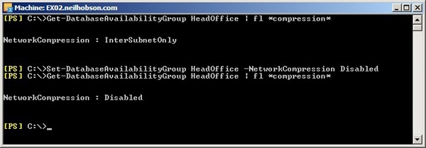
Figure 5: Enabling DAG Network Compression
The Failover Cluster
Now that you have your DAG customized to your taste, let’s take a look at how we can manage it. Earlier in this article, we saw that the Windows Failover Cluster components were installed onto each mailbox server when the Add-DatabaseAvailabilityGroup cmdlet was run. There are some worthwhile observations to make regarding the role of the failover cluster in Exchange 2010, when compared to its counterpart in Exchange 2007. For example, the red highlight box in Figure 6 shows the Failover Cluster Manager snap-in expanded out to reveal that the name of the cluster is derived from the name of the DAG. From examining the blue highlight boxes, it can also be seen that there are no Exchange-related cluster resources in the Services and applications node, such as those seen in Exchange 2007.
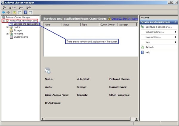
Figure 6: The Failover Cluster Manager Snap-in
What have been created, though, are cluster core resources for the DAG name, the DAG IP address and the file share witness, as shown in Figure 7:
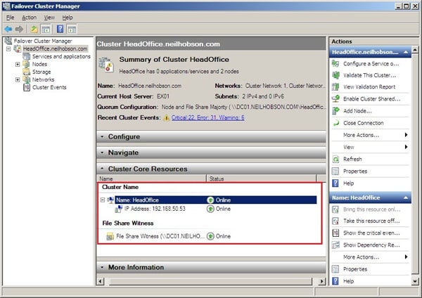
Figure 7: Cluster Core Resources
One of Microsoft’s design goals in Exchange 2010 was to ensure that an Exchange administrator can control a DAG and its Windows Failover Cluster requirements equally well from within the Exchange Management Console or the Exchange Management Shell, negating the need to perform any administrative duties within the Failover Cluster Manager snap-in. To highlight this, Figure 8 shows the DAG networks presented within the Exchange Management Console, whereas such objects were controlled within the Failover Cluster Manager snap-in in Exchange 2007.
In fact, in Figure 8, you can see that two networks have been created with their default names set to DAGNetwork01 and DAGNetwork02 respectively. The subnet information is also displayed and, as a result, you can see that DAGNetwork01 is actually the MAPI network, since it represents the 192.168.50.0 network, and that DAGNetwork02 is the Replication network, as it represents the 10.0.0.0 network.
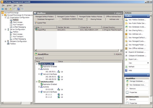
Figure 8: DAG Networks in the Exchange Management Console
If you have taken the time to rename your network connections on each mailbox server to differentiate between the MAPI and Replication network interfaces, it makes sense to rename the networks that you can see in Figure 8 as well so that they match, if only to make troubleshooting easier.
With that in mind, to change the display name of DAGNetwork01 to “MAPI Network”, the command below can be used. The same process can obviously be used to rename DAGNetwork02 to “Replication Network”:
|
1 |
Set-DatabaseAvailabilityGroupNetwork -Identity HeadOffice\DAGNetwork01 -Name "MAPI Network" |
Mailbox Database Copies
Before creating the DAG and adding the mailbox servers to it, the Exchange 2010 mailbox server role had already been installed on both servers before the start of this demonstration. As a result, a default mailbox database had already been created on each mailbox server and given the default name, which now has a format of “Mailbox Database n”, where “n” is a random 10-digit number; for example, the default mailbox database on server EX02 is called Mailbox Database 1796634876.
The reason for this default naming standard is that, in Exchange 2010, the mailbox database is now an organization object and not tied to any particular mailbox server. As a result, database names must be unique across the Exchange organization. As can be seen from the screen shots later in this article, the default databases have already been renamed to Mailbox Database 001 and Mailbox Database 002 on servers EX01 and EX02 respectively.
Now, even though a DAG has been created and both mailbox servers are members of this DAG, there still exists only a single copy of each mailbox database by default. To create a highly available mailbox database configuration, it is now necessary to ensure that a copy of Mailbox Database 001 exists on server EX02 and a copy of Mailbox Database 002 exists on server EX01. In this configuration, each mailbox server will initially host a single active database as well as a single passive copy of the active database hosted on the other server. To create this configuration, the Add-MailboxDatabaseCopy cmdlet can be used and, in the lab environment, the first command used is:
|
1 2 |
Add-MailboxDatabaseCopy -Identity "Mailbox Database 001" -MailboxServer EX02` -ActivationPreference 2 |
With this command, we can see that a copy of Mailbox Database 001 is being added to the mailbox server EX02. The ActivationPreference parameter is used to determine which database to activate if there are multiple databases available that meet the activation criteria used by the Active Manager process. The Active Manager process runs on each mailbox server in a DAG, and essentially decides which database copy to activate when the need arises. If multiple databases meet all the criteria, the activation preference is consulted and the database with the lowest value is activated. Since the primary copy of the database has an activation preference of 1, a value of 2 has been chosen for the second copy of this database.
The results of running the Add-MailboxDatabaseCopy cmdlet are shown in Figure 9:
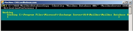
Figure 9: Adding a Mailbox Database Copy
To confirm that copies of Mailbox Database 001 now exist on both EX01 and EX02, it is possible to use the Get-MailboxDatabase cmdlet to consult the DatabaseCopies and Servers parameters, as shown in Figure 10. Then it’s just a question of re-running the Add-MailboxDatabaseCopy cmdlet for Mailbox Database 002, but this time specifying a target server of EX01. Once this cmdlet has completed, both databases have a copy that exist on the alternate mailbox server:
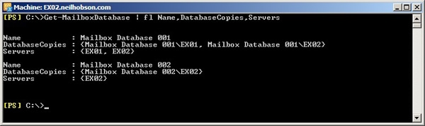
Figure 10: Checking ‘Mailbox Database 001’ Database Copies
Database Failovers
Now that our 2-node DAG is essentially built and configured, all that remains is to prove that the databases can be moved between the two mailbox server nodes. Before we do that though, let’s briefly cover some key terminology that Microsoft uses in this area: switchovers and failovers, collectively known as *overs (pronounced star-overs).
A switchover is an action performed by an administrator to move either a single database or all the databases on a mailbox server to an alternative mailbox server within the DAG. If the administrator moves all databases from one server to another, then this process is known as a server switchover. The most obvious example of when you might need to perform a server switchover is when applying an update rollup or service pack to an Exchange 2010 mailbox server. On the other hand, in the example I will present shortly, we will be performing a switchover of just a single database from server EX01 to server EX02 – a process known as a database switchover.
A failover is an automatic action performed by the system in response to a problem with either a single database or the entire mailbox server. Like switchovers, failovers can also apply to either a single mailbox database (a database failover) or the entire server (a server failover). I won’t be demonstrating a failover here, but I will perform a database switchover using the Exchange Management Console, although the Exchange Management Shell can also be used if you prefer.
Demonstrating a Switchover
The first thing to do is to obtain the status of the database copies. In Figure 11, you can see that the active copy of the database named Mailbox Database 001 is currently residing on server EX01, since the Copy Status column shows a value of Mounted for server EX01. Server EX02 contains a healthy copy of this database, which you can tell by virtue of the fact that the Copy Status column shows a value of Healthy for server EX02. Likewise, Mailbox Database 002 is active on server EX02 and has a healthy database copy on server EX01.
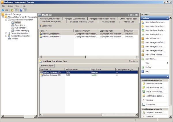
Figure 11: The Database Copy Status
To make the copy of Mailbox Database 001 on server EX02 the active copy, the following process is used:
- In the bottom pane shown in Figure 11, right-click the healthy copy of Mailbox Database 001 located on server EX02, and choose the Activate Database Copy… option from the context menu (as shown in Figure 12):
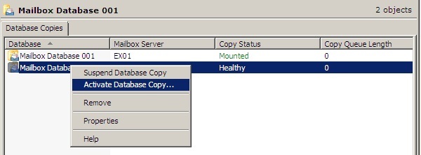
Figure 12: Activating a Database Copy
- Next, a window is presented that allows you to override the AutoDatabaseMountDial setting for this mailbox server. Shown in Figure 13, this setting essentially allows you to control whether or not the database will mount, depending on how many transaction log files may be missing. More information on the AutoDatabaseMountDial parameter can be found in the Exchange 2010 product documentation on the Set-Mailbox cmdlet.
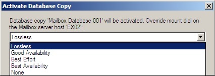
Figure 13: AutoDatabaseMountDial Override
- The database copy on server EX02 is then activated and, if the procedure is successful, the Exchange Management Console will now reflect this, as shown in Figure 14, where you can see that the Copy Status column now indicates that the copy of the database on server EX02 is Mounted.
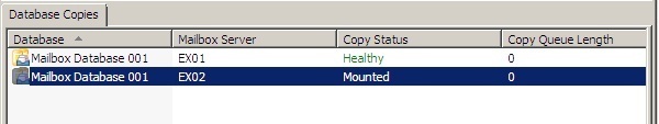
Figure 14: New Active Database Copy
To perform a complete server switchover, where all databases are moved from one mailbox server to another, the Switchover Server option can be selected from the action pane when the relevant mailbox server is highlighted in the EMC’s Server Configuration -> Mailbox view. I will leave you, the reader, to discover and test out these processes in your own time.
Summary
That concludes the final article of this two-part series on creating and configuring a two-node DAG solution using Exchange 2010. If you have followed both parts of this article, you will now have a solid understanding of the steps required to construct a simple two-node DAG, as well as how to configure and use it.
Whilst there is no doubt that Microsoft has produced a compelling mailbox database high availability feature in Exchange 2010, you should be fully aware that the DAG is only one aspect of a truly highly available messaging infrastructure. Other key components, such as the Client Access Server role, the Hub Transport server role, Active Directory, DNS, and so on, all have to be planned and implemented with Exchange 2010 high availability in mind.
Load comments