
The ADO.NET Entity Framework (EF) is object relational mapping software for ADO.NET, used to develop applications that interact with data. It provides a mapping between the relational database schemas and objects. This technology is helpful for architecting, designing and developing at a conceptual level without worrying about details. ADO.NET Entity Framework allows developers to program against the Entity Relationship (Object) model, as opposed to querying against the relational database, mainly concentrating on the data. The main benefit is to make data oriented applications maintenance friendly.
EF – Benefits
- The application won’t be tied to hard-coded dependencies on the storage schema or database.
- The conceptual model and the storage-specific schema mappings can change without changing the application code.
- Developers can work more easily with an object model that can be mapped to various storage schemas, and can be implemented in different databases.
- The ability to map multiple conceptual models to a single storage schema.
Model First Development was introduced in VS 2010, along with .NET Framework 4.0, and the essential idea behind the Entity Framework is to query the model, rather than the database. In this article I will walk through how to generate databases from the model.
Understanding the model
EF maps to the database tables using a model. This model is responsible for mapping the application’s entities and their relationships to the data held in the physical database. It’s a combination of three layers, and is stored as an Entity Data Model (.edmx) file. .edmxis an XML based file that consists of these 3 layers.
- Storage Layer: this is defined with Store Schema Definition Language (SSDL). Table structures and their relationships are defined here.
- Conceptual Layer: this is defined with Conceptual Schema Definition Language (CSDL). Business entities and their relationships are described in the conceptual schema.
- Mapping Layer. This is defined with Mapping Specification Language (MSL). It maps the conceptual schema to the storage schema. The mapping schema describes how the business entities map to the database schema, and how database tables map to the entities in the model.
If you right click on an .edmx file and open it with XML Text Editor, you can view the EDMX schema layers.
At runtime, the .edmx is split into three different files: .ssdl, .csdl and .msl.
To construct any database, we need define the tables for the data storage. Here, tables are mapped to entities, hence the need to have entities and their relationships defined in the model. The model can be created using an .edmx file in Entity Framework and each entity in a specific Entity Framework is mapped as a table inside the database, and each property in an entity is mapped to a corresponding column in the specified table.
Creating the model
Let us start by creating a Class Library Application in Visual Studio 2010, so that we can re-use the models. We select the Add ->new Item , then the Data tab in the Visual Studio 2010 Installed Templates list, and finally select ADO.NET Entity Data Model. We’ll name our .edmx ‘Company’, and click the Add button, in the lower right corner, as shown below.
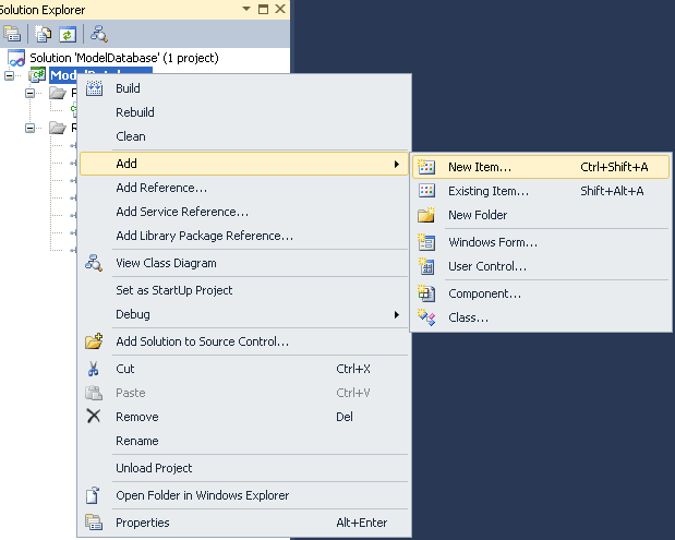
Figure 1: Adding a new item to the class library project.
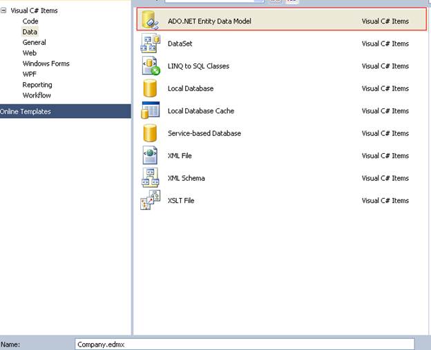
Figure 2: Adding Company.edmx to the project.
The moment we click the Add button, the Entity Data Model Wizard appears. This gives us two options to select from:
- Generate from database
- Empty model
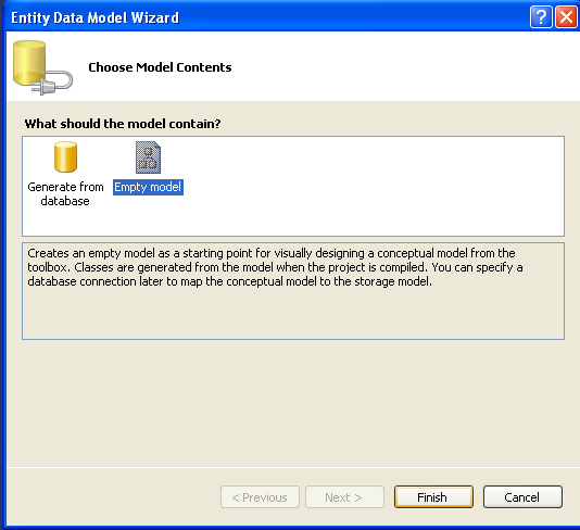
Figure 3: Adding an empty model.
We aren’t going to worry about the first option as we are interested in creating a database from the model only. We’ll select the second option, Empty model, and click the Finish button. As you can see from the screenshot above, this option creates an empty model as a starting point for visually designing a conceptual model from the toolbox. When the project is compiled, classes will be generated from the model. We’ll specify a database connection to map the conceptual model to the storage model later.
If you observe the Solution Explorer, it creates a new reference related to Entity Framework, System.Data.Entity, responsible for working with the Entity Framework related APIs. This reference is added only after adding an .edmx file.
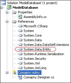
Figure 4: The System.Data.Entity reference, added after an .edmx file is created.
Creating entities in the .edmx
Now we need to define the model in this .edmx file by creating entities, which can be done by dragging items from the EF toolbox or from the model itself.
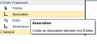
Figure 5: Entity Framework toolbar for creating entities and relationships between entities.
In a Company, we’ll have Employees, Departments and Managers as entities. Let’s create the Employee entity.
We right click on the .edmx file and Click Add â Entity as shown below.
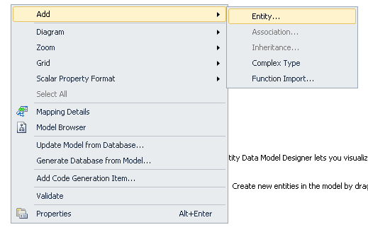
Figure 6: Adding a new entity to the Model.
A dialogue box for adding an Entity appears, as shown below.
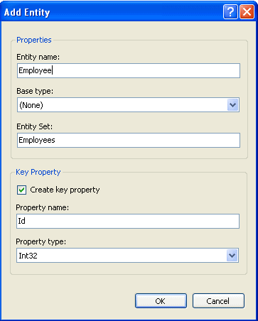
Figure 7: Creating the Employee entity.
We’ll name the entity ‘Employee’. The Entity Set is automatically pluralized by the IDE, based on the Entity Name.
It also creates a Key property – ID – of type Integer. This Key is called the Entity Key in the model, and mapped as the Primary Key in the database. If you do not want to create the Entity Key property for a particular entity you can uncheck this property. Next, we’ll press OK.
Now we have created an entity, we can start adding some more properties for it. There are two ways of doing this:
- Right click on the entity to add new properties such as EmpName, Description, DOB and Address.
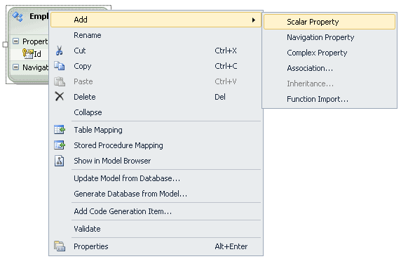
Figure 8: Creating scalar properties for the entities.
- 2. Select the Id property and hit enter to add some more scalar properties (scalar properties map to a single field in the storage layer).
Editing entity properties
To edit the attributes for entity properties, you select the property and right click it, then navigate to properties. The properties that you set are reflected in the database that is going to be created from the model.
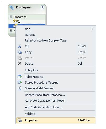
Figure 9: Selecting the Employee entity’s properties.
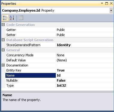
Figure 10: Editing the Employee entity’s properties.
Note that here the identity property for the primary key column is set automatically by the IDE. The Nullable attribute allows or disallows any null values inside the column.
Creating more entities for the model
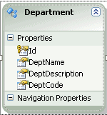
Now let us create a department entity with the properties Id, DeptName, DeptDescription, and DeptCode, as shown to the left.
Fig11: The Department entity.
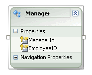
Let us also create a Manager entity with ManagerId, EmployeeID as properties. The key for this entity is the combination of ManagerId and EmployeeID. One employee can report to multiple managers.
Figure 12: The Manager entity.
Applying relationships to the entities
An employee cannot be member of multiple departments. A department, however, should accommodate multiple employees, so the relationship between employee and department is one to many. Let us add a new association between these two tables. For this, we right click on the model, and click Add â Association…
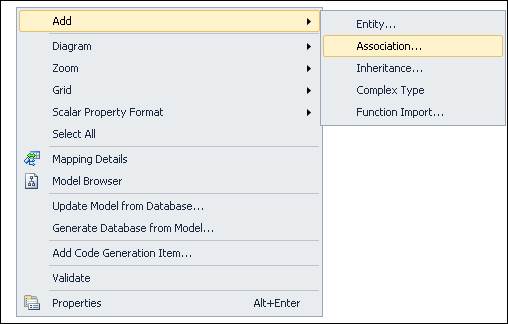
Figure 13: Adding an Association relationship to the table.
This opens the following window, with the option to add relationships between these two tables.
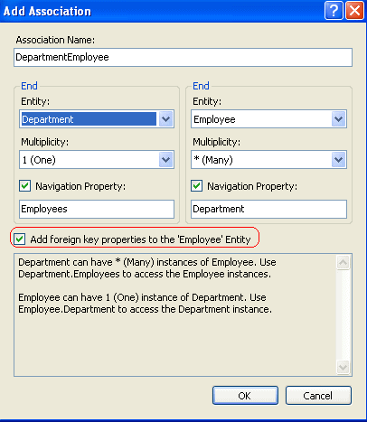
Figure 14: Adding an association between Employee and Department.
We need to make provision for the department entity to have many instances of the Employee entity, so we map the relationship between the department and the Employee entities as one to many, as shown above. Clicking the check box “Add foreign key properties to the ‘Employee’ entity” helps to create the foreign key relationships between these two tables automatically.
If we observe the Employee entity, we notice that departmentid is being added to the employees table for the foreign key relationship in the database.
A manager can have more than one employee reporting to him, and an employee can report to multiple managers, so the relationship between the Employee entity and the manager entity is many to many. We need to add a many to many association between these two entities. Because a manager is also an employee of the company, the manager class gets inherited from the Employee class. To add this inheritance relationship, right click on the model and select Add âInheritance…
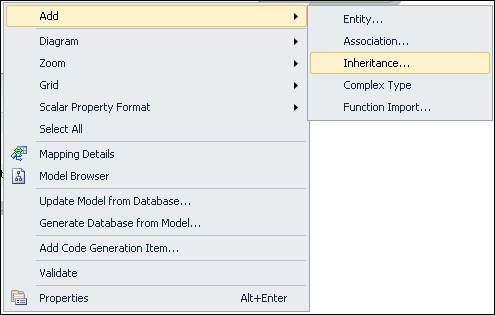
Figure 15: Adding an inheritance relationship for entities.
In the dialog box, select Employee as the base entity as and Manager as the derived entity.
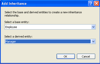
Figure 16: Adding inheritance between the Employee and Manager entities.
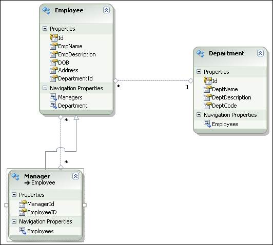
Figure 17: The final model after applying all the relationships.
We’ve now finished adding relationships between our entities, and are ready to generate our database.
Changing DatabaseSchema Name
Entity Framework Model uses dbo as the default schema name. In order to change that, right click on the .edmx in the VS2010 IDE, and click on Properties. The ConceptualEntityModel properties window appears as shown below. Make sure that you change the name according to the project, so that the script files are generated accordingly.
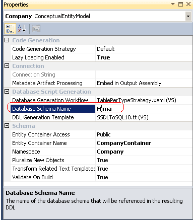
Figure 18: Conceptual Model Properties.
If we look at Company.edmx in the automatic editor selector, we can view the XML schema code that’s been generated from the design. SSDL, CSDL, and MSL are created by the IDE, based on the entities and their relationships. Each time we make changes to the model, this schema gets recreated. To view this, we need to right click on the .edmx file and open with the XML (Text) Editor.
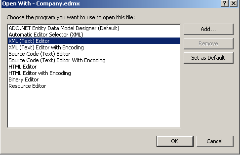
Figure 19: Opening the .edmx with the XML editor.
Here we can examine how the Entities and their relations are mapped in the conceptual model, and how the storage schema and conceptual schema are actually mapped in the mapping layer.
We can also examine the Company.designer.cs file, a partial class inherited from ObjectContext.
All the entities that are created from the IDE inherit from Entityobject. Their code is generated automatically with properties and datacontract attributes. Whenever we modify and save the .edmx file, the classes or the automatic code are regenerated by the IDE.
Generating the database from the model
Now we need to right click and select Generate Database from the Model, from the context menu.
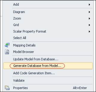
Figure 20: Generate Database from the Model
We need to have an empty or existing database created in SQL Server to generate a database from the model. I have created an empty database, called Company, in SQL Server 2008. If you do not have existing connections, then click on new Connection button and specify your credentials, as shown below.
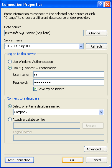
Figure 21: Connection string credentials.
Now, choose the appropriate data connection from the dropdown list, as shown below. Here we also have the option to save the connection string in app.config, which contains connection string metadata and various settings for the project. The syntax is somewhat different from the normal connection string.
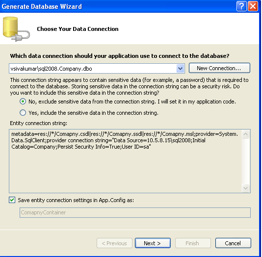
Figure 22: Choosing the data connection for the creation of a database from our model.
Pressing Next generates a file called Company.edmx.sql. Note that the constraints, foreign key relationships, and primary keys in the tables are created based on the properties specified in the model.
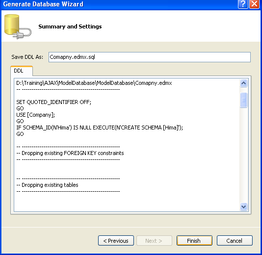
Figure 23: The generated Company.edmx.sql file
Finally, click on the Finish button. The IDE creates this .sql script file for us:
|
1 2 3 4 5 6 7 8 9 10 11 12 13 14 15 16 17 18 19 20 21 22 23 24 25 26 27 28 29 30 31 32 33 34 35 36 37 38 39 40 41 42 43 44 45 46 47 48 49 50 51 52 53 54 55 56 57 58 59 60 61 62 63 64 65 66 67 68 69 70 71 72 73 74 75 76 77 78 79 80 81 82 83 84 85 86 87 88 89 90 91 92 93 94 95 96 97 98 99 100 101 102 103 104 105 106 107 108 109 110 111 112 113 114 115 116 117 118 119 120 121 122 123 124 125 126 127 128 129 130 131 132 133 134 135 136 137 138 139 140 141 142 143 144 |
-- -------------------------------------------------- -- Entity Designer DDL Script for SQL Server 2005, 2008, and Azure -- -------------------------------------------------- -- Date Created: 04/25/2011 17:30:49 -- Generated from EDMX file: D:\Training\AJAX\ModelDatabase\ModelDatabase\Company.edmx -- -------------------------------------------------- SET QUOTED_IDENTIFIER OFF; GO USE [Company]; GO IF SCHEMA_ID(N'Hima') IS NULL EXECUTE(N'CREATE SCHEMA [Hima]'); GO -- -------------------------------------------------- -- Dropping existing FOREIGN KEY constraints -- -------------------------------------------------- -- -------------------------------------------------- -- Dropping existing tables -- -------------------------------------------------- -- -------------------------------------------------- -- Creating all tables -- -------------------------------------------------- -- Creating table 'Employees' CREATE TABLE [Hima].[Employees] ( [Id] int IDENTITY(1,1) NOT NULL, [EmpName] nchar(4000) NOT NULL, [EmpDescription] nvarchar(max) NOT NULL, [DOB] datetime NOT NULL, [Address] nvarchar(max) NOT NULL, [DepartmentId] int NOT NULL ); GO -- Creating table 'Departments' CREATE TABLE [Hima].[Departments] ( [Id] int IDENTITY(1,1) NOT NULL, [DeptName] nvarchar(max) NOT NULL, [DeptDescription] nvarchar(max) NOT NULL, [DeptCode] nchar(4000) NOT NULL ); GO -- Creating table 'Employees_Manager' CREATE TABLE [Hima].[Employees_Manager] ( [ManagerId] int NOT NULL, [EmployeeID] int NOT NULL, [Id] int NOT NULL ); GO -- Creating table 'EmployeeManager' CREATE TABLE [Hima].[EmployeeManager] ( [Employees_Id] int NOT NULL, [Managers_Id] int NOT NULL ); GO -- -------------------------------------------------- -- Creating all PRIMARY KEY constraints -- -------------------------------------------------- -- Creating primary key on [Id] in table 'Employees' ALTER TABLE [Hima].[Employees] ADD CONSTRAINT [PK_Employees] PRIMARY KEY CLUSTERED ([Id] ASC); GO -- Creating primary key on [Id] in table 'Departments' ALTER TABLE [Hima].[Departments] ADD CONSTRAINT [PK_Departments] PRIMARY KEY CLUSTERED ([Id] ASC); GO -- Creating primary key on [Id] in table 'Employees_Manager' ALTER TABLE [Hima].[Employees_Manager] ADD CONSTRAINT [PK_Employees_Manager] PRIMARY KEY CLUSTERED ([Id] ASC); GO -- Creating primary key on [Employees_Id], [Managers_Id] in table 'EmployeeManager' ALTER TABLE [Hima].[EmployeeManager] ADD CONSTRAINT [PK_EmployeeManager] PRIMARY KEY NONCLUSTERED ([Employees_Id], [Managers_Id] ASC); GO -- -------------------------------------------------- -- Creating all FOREIGN KEY constraints -- -------------------------------------------------- -- Creating foreign key on [Employees_Id] in table 'EmployeeManager' ALTER TABLE [Hima].[EmployeeManager] ADD CONSTRAINT [FK_EmployeeManager_Employee] FOREIGN KEY ([Employees_Id]) REFERENCES [Hima].[Employees] ([Id]) ON DELETE NO ACTION ON UPDATE NO ACTION; GO -- Creating foreign key on [Managers_Id] in table 'EmployeeManager' ALTER TABLE [Hima].[EmployeeManager] ADD CONSTRAINT [FK_EmployeeManager_Manager] FOREIGN KEY ([Managers_Id]) REFERENCES [Hima].[Employees_Manager] ([Id]) ON DELETE NO ACTION ON UPDATE NO ACTION; -- Creating non-clustered index for FOREIGN KEY 'FK_EmployeeManager_Manager' CREATE INDEX [IX_FK_EmployeeManager_Manager] ON [Hima].[EmployeeManager] ([Managers_Id]); GO -- Creating foreign key on [DepartmentId] in table 'Employees' ALTER TABLE [Hima].[Employees] ADD CONSTRAINT [FK_DepartmentEmployee] FOREIGN KEY ([DepartmentId]) REFERENCES [Hima].[Departments] ([Id]) ON DELETE NO ACTION ON UPDATE NO ACTION; -- Creating non-clustered index for FOREIGN KEY 'FK_DepartmentEmployee' CREATE INDEX [IX_FK_DepartmentEmployee] ON [Hima].[Employees] ([DepartmentId]); GO -- Creating foreign key on [Id] in table 'Employees_Manager' ALTER TABLE [Hima].[Employees_Manager] ADD CONSTRAINT [FK_Manager_inherits_Employee] FOREIGN KEY ([Id]) REFERENCES [Hima].[Employees] ([Id]) ON DELETE NO ACTION ON UPDATE NO ACTION; GO -- -------------------------------------------------- -- Script has ended -- -------------------------------------------------- |
This script can be given to the DBA to run, creating the database. Or, we can right click on the script file and press Execute SQL or Control + Shift +E, to run a script against SQL Server 2008 database from the IDE.
The SQL script is generated from the SSDL contained in the .edmx file. This script contains lots of DDL statements to create the database tables, which correspond to the tables described in the SSDL. Entities are mapped as tables in the database and scalar properties are mapped as columns in the corresponding tables.
Summary
In this article we have learnt how to create a database from the model in EF 4.0, an approach also called ‘Model First’. We’ve looked at the structure of an .edmx file, and its significance, and learnt how to create entities, properties for the entities, and relationships between the entities. As we’ve seen, Model First Development helps to create a model for the entities, then has Visual Studio 2010 generate the DDL to create a database with matching tables, columns and relationships for the entities.
This document contains proprietary information and is protected by copyright law.
Copyright © 2026 Red Gate Software Limited. All rights reserved
Load comments