
Introduction
In a Cluster Continuous Replication (CCR) environment, each node of the cluster will usually have two network interfaces configured. One network interface will be used for client communications whilst the other will be used for intra-cluster communications. However, there are additional configuration options that you should consider when designing the network configuration of your CCR environment. In Exchange 2007 Service Pack 1, a new feature was introduced that allowed additional redundant networks to be added to a CCR environment for the purposes of log shipping and database seeding. With specific networks dedicated to log shipping and database seeding, the remaining network is dedicated to its task of servicing client communications. Such a configuration avoids situations where the network that is servicing client communications also has to process a large number of transaction logs. Additionally, since redundant networks are used, overall high availability of the CCR environment is enhanced.
In this article, I am going to describe a highly-available configuration that is required to support multiple redundant networks used for the purposes of log shipping and database seeding. The actual configuration process is slightly different depending on whether the CCR environment is being implemented on Windows 2003 or Windows 2008, so I will be highlighting the differences where appropriate. However, please note that the focus of this article is the Windows 2008 operating system. In the configuration that I am describing within this article, each node of the CCR environment is equipped with four network interfaces configured in the following fashion:
- Two network interfaces are configured as a network team and will be configured as the public network used for client connectivity.
- A single network interface will be configured as a private network for intra-cluster communications as well as transaction log shipping.
- Another single network interface will also be configured as a private network that is also used for intra-cluster communications as well as transaction log shipping.
With this configuration, Exchange will select one of the private networks for log shipping. If this private network were to fail, Exchange will select the remaining private network and will only revert to using the public network should both private networks fail or be otherwise unavailable.
Figure 1 shows this configuration, including the IP addresses in use. The cluster node server names are CCRA and CCRB respectively.
Figure 1: CCR Environment with Three Networks
The advantage of having two separate network interfaces configured as private networks is that this configuration ensures that there is full redundancy for the private networks. However, this does not mean that it’s not possible to implement redundant networks for log shipping and database seeding if there are only three network interfaces in each cluster node. It’s perfectly possible but the configuration will be slightly different. With just three network interfaces available, the following configuration will be possible:
- Two network interfaces configured as a network team and configured as the public network used for client connectivity.
- A single network interface configured as a private network for intra-cluster communications as well as transaction log shipping.
With this configuration, Exchange will use the private network for log shipping and will only revert to using the public network should the private network fail or be otherwise unavailable. Therefore, utilizing four network interfaces in each cluster node gives more flexibility to the design and is the configuration that I am using in this article.
Network Teaming
Network teaming is simply the process whereby multiple network interfaces are grouped together to form a single logical network interface, with the objective being to offer fault tolerance and load balancing. In the network interface configurations mentioned previously within this article, it may have been noticed that only the public network interface is teamed. This configuration exists because Microsoft does not support teamed network card configurations for the private network interfaces in a clustered environment. More information on this can be found in Microsoft knowledgebase article 258750.
Rename Network Interfaces
It’s recommended to rename the network connections so that they reflect the role that they are performing, as this can be very helpful when troubleshooting issues. Throughout this article, the network interfaces will be referred to using the following names:
- Public. This is the teamed network interface that services client connectivity.
- Private1 and Private2. These are the two private network interfaces that service intra-cluster communications and will be configured for transaction log shipping. They can also be used for database seeding.
Configuration Procedure
Now that the background information on the network configuration has been described along with the setup that will be configured in this article, it’s time to take a look at the actual configuration process involving continuous replication host names. These are additional host names that are assigned to each cluster node for the purposes of transaction log shipping and database seeding. The configuration process will be divided into the following broad stages:
- Choose the continuous replication host names and IP addresses.
- Configure the private network interfaces as mixed networks in the cluster management application.
- Disable strict name checking. This is only required if a CCR environment is being deployed on the Windows 2003 operating system.
- Configure name resolution.
- Enable NetBIOS on the private network interfaces. This is only required if a CCR environment is being deployed on the Windows 2008 operating system
- Enable the continuous replication host names.
- Check that the correct continuous replication host names are being used.
Choose Replication Host Names and IP Addresses
Regardless of whether you are using Windows 2003 or Windows 2008 as your operating system of choice for your CCR environment, you must first plan up front the continuous replication host names and IP addresses that will be used. Each private network configured in the CCR environment requires a continuous replication host name and IP address assigned to it in addition to the existing IP address it will have. For example, it can be seen from Figure 1 that the cluster node CCRA has a private network interface called Private1 configured with the IP address of 10.10.10.1. This private network interface now needs another IP address assigned to it and this IP address linked with a continuous replication host name. Extrapolating this information out, each cluster node within the CCR environment described within this article has two continuous replication host names and IP addresses assigned to it, since two independent private networks are being used for this purpose. It’s these continuous replication host names that are used to identify which of the networks are used to ship the transaction logs from one cluster node to the other. It’s possible to choose any host names but I personally find it useful to ensure that they are linked in some way with each cluster node. For example, in the CCR environment that is being described within this article the two cluster nodes are called CCRA and CCRB. Therefore, for cluster node CCRA, I’ve chosen continuous replication host names of CCRAREP1 and CCRAREP2 whilst for cluster node CCRB I’ve chosen continuous replication host names of CCRBREP1 and CCRBREP2. On cluster node CCRA, the continuous replication host name CCRAREP1 will be assigned to the network interface called Private1, whilst the continuous replication host name CCRAREP2 will be assigned to the network interface called Private2. A similar configuration will be applied to the cluster node CCRB. Each continuous replication host name is assigned a new IP address.
Putting all this information together, the example CCR environment configuration is shown in Figure 2. Note that the public network has been removed for reasons of clarity.
Figure 2: CCR Environment with Continuous Replication Host Names
Mixed Cluster Networks
In a typical cluster configuration consisting of a single public network and a single private network, the public network will be configured within the cluster management application as a mixed cluster network. This means that this network will be used to process client communications as well as intra-cluster communications. Intra-cluster communication is often referred to as the heartbeat. Conversely, the private network will be configured within the cluster management application as a private network, meaning that it will only be used for intra-cluster communications.
One of the main configuration differences required when implementing redundant cluster networks for continuous replication host names is the fact that the private networks must be configured as mixed cluster networks. When using Windows 2003, this is achieved using the Cluster Administrator snap-in whilst in Windows 2008 it can be achieved using the Failover Cluster Management snap-in. Therefore, in the environment being described within this article, both the Private1 and Private2 networks have been configured as mixed cluster networks as shown in Figure 4, where the Failover Cluster Management snap-in is being used. Figure 3 shows the configuration when using the Cluster Administrator application on Windows 2003.
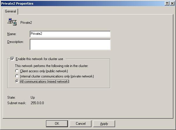
Figure 3: Mixed Cluster Network on Windows 2003
Figure 4: Mixed Cluster Network on Windows 2008
Configuring the private networks as mixed networks within the cluster management application may seem counter intuitive based on the fact that mixed cluster networks generally service client communications. However, even though the private networks will not be servicing client communications in this case, they must still be configured as mixed cluster networks within the cluster management application so that cluster resources can be created for them.
Strict Name Checking (Windows 2003)
An additional configuration change must be made if the CCR environment has been deployed using Windows 2003. Strict name checking must be disabled on both cluster nodes to ensure that the Windows 2003 operating system correctly listens for connections being made using the continuous replication host names. This change does not need to be made if the CCR environment has been deployed using the Windows 2008 operating system.
To make this change, the registry must be modified on both cluster nodes. The required registry information is as follows:
|
1 2 3 |
Key: HKEY_LOCAL_MACHINE\System\CurrentControlSet\Services\lanmanserver\parameters DWORD Value: DisableStrictNameChecking Value: 1 |
After making this registry change, the server must be restarted for the change to take effect. Remember, this change must be made on both cluster nodes of the CCR environment.
Name Resolution
Regardless of whether the CCR environment is deployed using Windows 2003 or Windows 2008, some aspects of name resolution must be configured on each private network interface being used for continuous replication. There are two configuration requirements to complete.
The first requirement is to clear the check box named Register this connection’s addresses in DNS. To do this in Windows 2008, follow these steps:
- Bring up the properties of the network interface.
- Select the Internet Protocol Version 4 (TCP/IPv4) object and then click the Properties button.
- In the resulting properties window, click the Advanced button.
- In the Advanced TCP/IP settings window, click the DNS tab.
- Clear the check box named Register this connection’s addresses in DNS as shown in Figure 5.
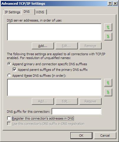
Figure 5: DNS Configuration Change
Next the continuous replication host names must be entered in the Domain Name System (DNS), or host file entries must be created. Generally, DNS is recommended where possible as tracking manually created host file entries can sometimes be problematic. Therefore, in this article it is assumed that static DNS records have been created for the continuous replication host names. Don’t underestimate the importance of this step as name resolution plays a vital role in allowing the log shipping or database seeding to take place via the redundant networks being configured. Therefore, in the example environment being described within this article four static DNS A records have been created, one for each continuous replication host name. These records are highlighted in Figure 6.
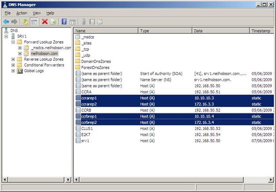
Figure 6: DNS Static Records
Enable NetBIOS (Windows 2008)
If the CCR environment has been deployed using the Windows 2008 operating system, there is another important networking configuration that must be made on each private network interface being configured with continuous replication host names. Specifically, NetBIOS must be enabled on the private network interface to ensure that the new network name resource, that will be created later, will come online successfully. To enable NetBIOS on the private network interfaces, follow these steps:
- Bring up the properties of the network interface.
- Select the Internet Protocol Version 4 (TCP/IPv4) object and then click the Properties button.
- In the resulting properties window, click the Advanced button.
- In the Advanced TCP/IP settings window, click the WINS tab.
- Select the Enable NetBIOS over TCP/IP button as shown in Figure 7.
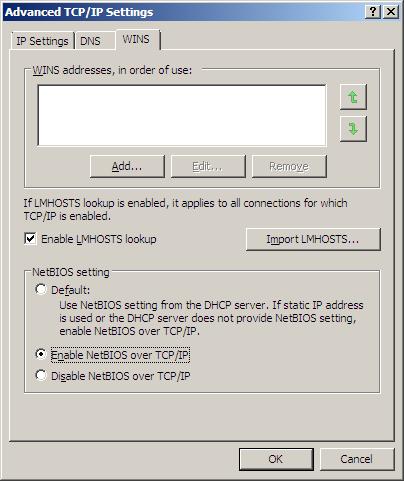
Figure 7: Enabling NetBIOS
Enable Continuous Replication Host Names
The next step of the configuration process is to enable the continuous replication host names on the CCR environment. To do this, the Enable-ContinuousReplicationHostName cmdlet is run. Since the example environment in this article is using four continuous replication host names, it follows that the Enable-ContinuousReplicationHostName cmdlet will need to be run a total of four times to complete the required configuration. The parameters used in this cmdlet are as follows:
- Identity. This parameter is used to identify the name of the Clustered Mailbox Server (CMS) being configured. The CMS is the server name that the Outlook clients connect to in a CCR environment.
- TargetMachine. The TargetMachine parameter is used to identify the cluster node that is being configured.
- HostName. This parameter is the actual continuous replication host name being configured on the server referenced via the TargetMachine parameter.
- IPV4Address. The IPV4Address parameter is the IP address associated with the HostName parameter that has just been discussed. It’s therefore useful to think of the HostName and IPV4Address parameters as a logical pairing.
- Confirm. When scripting PowerShell cmdlets, it can sometimes be useful to prevent the Exchange Management Shell from prompting you for confirmation. In this example, the Confirm parameter will be used to ensure that prompts for confirmation are not encountered during the running of the cmdlet.
Here are the four cmdlets that will be run to enable continuous replication host names within the example CCR environment being described within this article:
|
1 2 3 4 5 6 7 8 |
Enable-ContinuousReplicationHostName -Identity E2K7 -TargetMachine CCRA ` -HostName CCRAREP1 -IPV4Address 10.10.10.3 -Confirm:$false Enable-ContinuousReplicationHostName -Identity E2K7 -TargetMachine CCRA ` -HostName CCRAREP2 -IPV4Address 172.16.3.3 -Confirm:$false Enable-ContinuousReplicationHostName -Identity E2K7 -TargetMachine CCRB ` -HostName CCRBREP1 -IPV4Address 10.10.10.4 -Confirm:$false Enable-ContinuousReplicationHostName -Identity E2K7 -TargetMachine CCRB ` -HostName CCRBREP2 -IPV4Address 172.16.3.4 -Confirm:$false |
It can be useful to have the cluster management program open before running these cmdlets, as it’s possible to see that a new cluster group is created each time that one of the cmdlets is run. For example, Figure 8 shows the Windows 2008 Failover Cluster Management application after the running of the first cmdlet listed above.
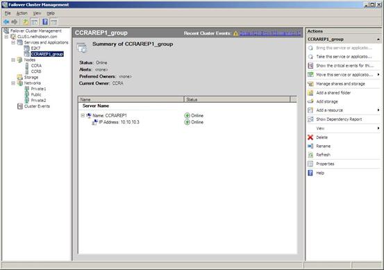
Figure 8: New Cluster Resource Group
It was discussed earlier in this article that NetBIOS must be enabled on the private network interfaces in order that the cluster resources can be brought online successfully. If this is not performed the following error will be seen when running the Enable-ContinuousReplicationHostName cmdlet:
Cluster Common Failure Exception: Failed to bring cluster resource Network Name (name) in cluster group (cluster group name) online. The event log may contain more details. Cluster Common Failure Exception: The cluster resource could not be brought online by the resource monitor. (Exception from HRESULT: 0x8007139A)
Figure 9 shows this error with the Exchange Management Shell.
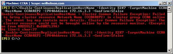
Figure 9: Resource Error in Exchange Management Shell
Within the Failover Cluster Management application, it can be seen that the corresponding Network Name resource has failed to come online, as can be seen in Figure 10.
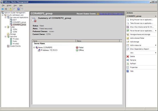
Figure 10: Resource Error in Failover Cluster Management
Once NetBIOS has been enabled on the private network interface, the configuration process can continue successfully as shown in Figure 11 and Figure 12. Note that a new cluster group has been created for each continuous replication host name.
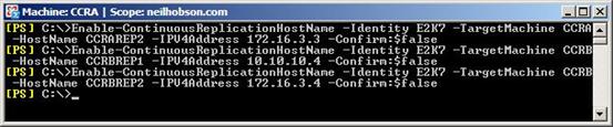
Figure 11: Enabling Continuous Replication Host Names
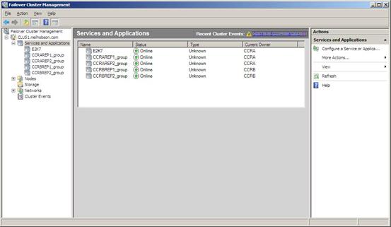
Figure 12: Continuous Replication Host Name Cluster Groups
Log Shipping Using Continuous Replication Host Names
Now that continuous replication host names have been enabled, it will be satisfying to confirm that Exchange is actually making use of these networks for log shipping purposes, rather than using the public network. To do this, it’s possible to examine the output of the Get-ClusteredMailboxServerStatus cmdlet as shown in Figure 13.

Figure 13: Get-ClusteredMailboxServerStatus Output
In Figure 13 it can be seen that the OperationalReplicationHostNames parameter contains the full list of continuous replication host names available for the CCR environment to use for log shipping purposes. In the example configuration presented within this article, there are two redundant networks available for use and the Microsoft Exchange Replication Service is responsible for choosing between them. It can be seen from Figure 13 that the InUseReplicationHostNames parameter shows which of the continuous replication host names has been selected by the Microsoft Exchange Replication Service for use.
The Microsoft Exchange Replication Service checks the status of the networks every five minutes and adjusts the configuration as required. For example, if the private network associated with the continuous replication host names CCRAREP2 and CCRBREP2 is disabled, the Microsoft Exchange Replication Service then chooses the remaining redundant network as can be seen in Figure 14. Notice how the CCRAREP2 and CCRBREP2 host names are now classified as FailedReplicationHostNames.
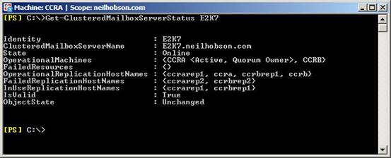
Figure 14: New Network in Use
Database Seeding via Redundant Networks
There may be occasions where it’s a requirement to re-seed one or more databases in a CCR environment. Naturally, re-seeding one or more large databases can cause a significant amount of network traffic to be generated and consequently it is desirable to ensure that this re-seeding process takes place using one of the redundant networks that have been configured.
To do this, it’s possible to use the DataHostNames parameter of the Update-StorageGroupCopy cmdlet. With this parameter, a maximum of two redundant networks can be specified although note that only one network can be used at a time. In other words, it’s not possible to perform a parallel seeding operation across two networks at the same time. In the scenario where it’s a requirement to re-seed the default mailbox database in the default first storage group from cluster node CCRA to cluster node CCRB, the cmdlet that can be used to take advantage of one of the redundant networks is:
|
1 |
Update-StorageGroupCopy "E2K7\First Storage Group" -DataHostNames CCRAREP1 |
Summary
CCR is an excellent high availability solution that can be deployed with just two network interfaces in each cluster node. However, there’s no doubt that the ability to deploy redundant networks using the continuous replication host name feature of Exchange 2007 Service Pack 1 greatly enhances the overall performance and high availability of a CCR environment. If you are about to implement a CCR environment, be sure to give due thought to implementing redundant networks for the purposes of log shipping and database seeding. In particular, take the time to decide whether you should be implementing multiple redundant private network interfaces as described within this article.
Load comments